Cable-cutter device

a cable cutter and aircraft technology, applied in the direction of mine sweeping, transportation and packaging, vehicular safety arrangments, etc., can solve the problems of difficult to see a cable having a diameter of 1 centimeter (cm) or 2 cm, a significant danger for helicopters, and telephone cables or high-voltage electricity cables

Active Publication Date: 2010-03-18
EUROCOPTER
View PDF16 Cites 5 Cited by
  • Summary
  • Abstract
  • Description
  • Claims
  • Application Information

AI Technical Summary

Benefits of technology

[0030]In the second stage, the cable then reaches the first and second sharp edges located at the end of the notch. Since the cable has already been partially nicked by the rotary blade, the first and second sharp edges can cut through it wit

Problems solved by technology

Cables, such as telephone cables or high-voltage electricity cables, constitute a significant danger for helicopters.
Because of the kinds of mission that they perform, helicopters fly at low altitude and run the risk at any time of coming into collision with a cable.
Even if the pilot of the helicopter pays particular attention, it remains difficult to see a cable having a diameter of 1 centimeter (cm) or 2 cm, for example.
In forward flight, the helicopter thus runs the risk of striking a cable.
Under such circumstances, the cable slides along the cockpit and then comes into contact with the rotor mast or else with the landing gear, and that can lead to a catastrophic situation.
It should be observed that most accidents that occur during low-altitude flig

Method used


Image

  • Cable-cutter device
  • Cable-cutter device
  • Cable-cutter device

Examples


Embodiment Construction

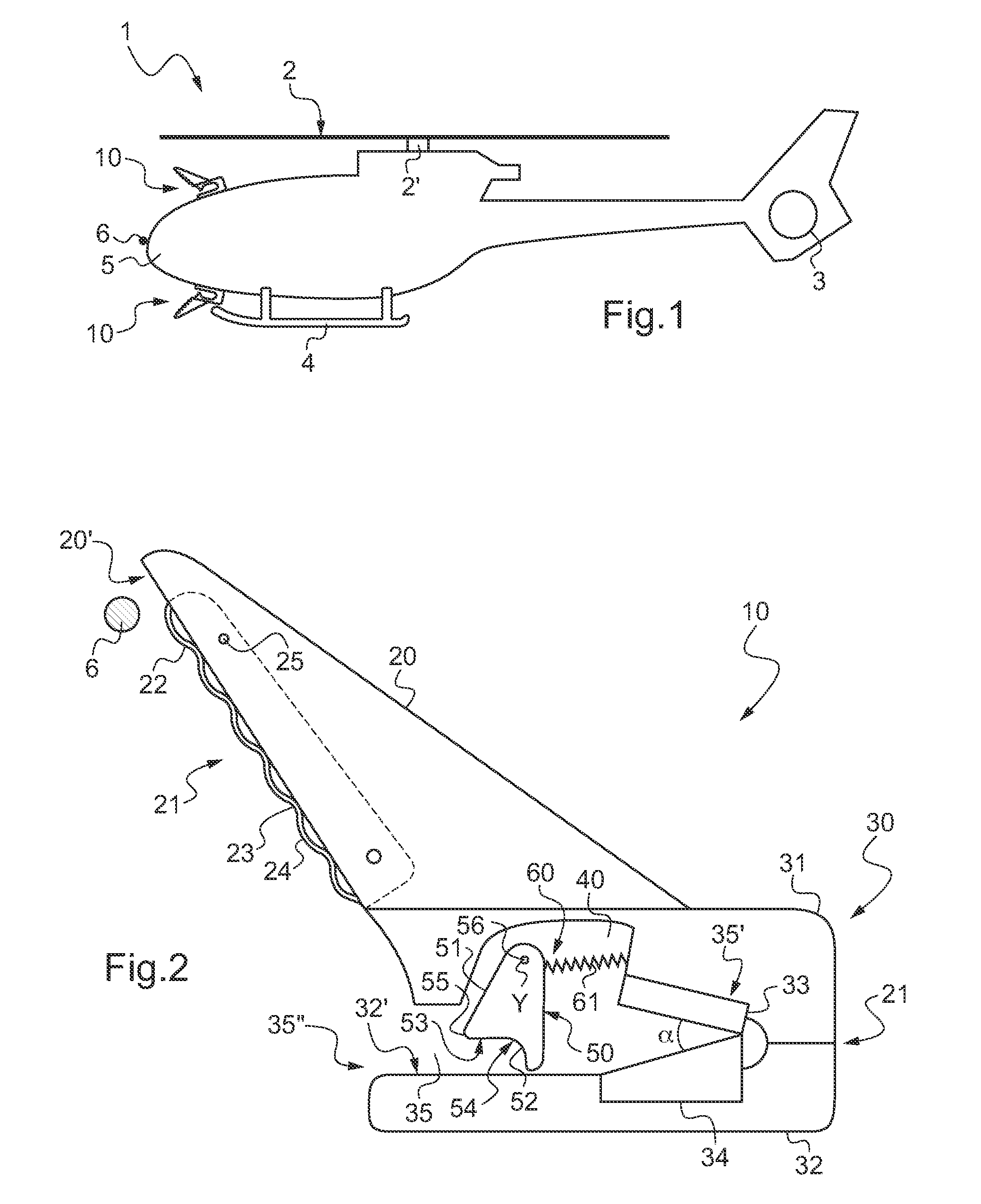
[0055]FIG. 1 shows an aircraft, more precisely a helicopter 1, provided with a main lift and propulsion rotor 2 and with a tail rotor 3.

[0056]The main rotor 2 is driven by an engine installation via its rotor mast 2′.

[0057]The helicopter 1 also includes skid landing gear 4.

[0058]In order to ensure that the rotor mast 2′ and the landing gear 4 are not struck by a suspended cable 6 during forward flight, the helicopter 1 is fitted with two cable-cutter devices 10 arranged above and below its cockpit 5.

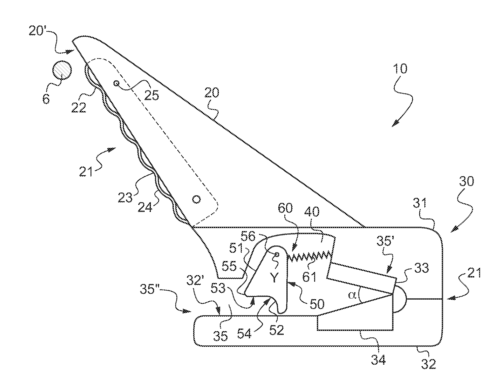
[0059]FIG. 2 shows the cable-cutter device 10 of the invention.

[0060]This device 10 for cutting cables 6 has a jaw 30 comprising a top portion 31 and a bottom portion 32 interconnected at one end only.

[0061]Thus, the top and bottom portions 31 and 32 define and surround a notch 35.

[0062]The notch 35 is blind in that it presents an upstream end 35″ that is open to the outside, and a downstream end 35′ that is closed by an end wall. It should be observed that the zone Z1 of fastening betwe...


PUM

PropertyMeasurementUnit
Angleaaaaaaaaaa

Abstract

A device (10) for cutting through cables (6) is provided with a jaw (30) having a top portion (31) and a bottom portion (32) which together define a notch (35). The device (10) is provided with a first and second stationary and co-operating sharp edges (33, 34) arranged at a downstream end (35′) of the notch (35) so as to form an angle between each other. The device further includes a rotary blade (50) provided with a body (51) having a tapering side (52), the body (51) being fastened to one of the portions (31, 32) of the jaw (33) so that the tapering side (52) is arranged in the notch (35) upstream from the first and second sharp edges (33, 34).

Description

FIELD OF THE INVENTION[0001]The present invention relates to a cable-cutter device for an aircraft, and more particularly an aircraft of the helicopter type. The invention thus lies in the technical field of aircraft cable-cutters.BACKGROUND OF THE INVENTION[0002]Thus, document U.S. Pat. No. 1,273,287 forms part of the technological background and not part of the technical field of the invention. That document describes a cable cutter suitable for being arranged on a bayonet and making use only of a pivoting knife in order to cut through said cables.[0003]Cables, such as telephone cables or high-voltage electricity cables, constitute a significant danger for helicopters.[0004]Because of the kinds of mission that they perform, helicopters fly at low altitude and run the risk at any time of coming into collision with a cable. Even if the pilot of the helicopter pays particular attention, it remains difficult to see a cable having a diameter of 1 centimeter (cm) or 2 cm, for example.[0...

Claims


Application Information

Patent Timeline
IPC IPC(8): B26B27/00
CPCB64C27/006B26D2011/005B26D11/00B60R19/545B63G7/04B26D5/38B26D3/08
Inventor CLAEYS, GERALD
Owner EUROCOPTER
Why Eureka
Try Eureka