
Reactive power compensation in solar power system

a solar power system and reactive power technology, applied in the direction of dc-ac conversion without reversal, process and machine control, instruments, etc., can solve the problems of undue stress on transmission lines, transformers and other electrical components

Active Publication Date: 2010-03-18
GENERAL ELECTRIC CO
View PDF10 Cites 76 Cited by
  • Summary
  • Abstract
  • Description
  • Claims
  • Application Information

AI Technical Summary

Problems solved by technology

Furthermore, excessive reactive power flow that causes rises in voltage may put undue stress on transmission lines, transformers and other electrical components.
Further, power factor control may occasionally result in an undesirable action such as introducing capacitance to inherently maintain a desired voltage.

Method used


Image

  • Reactive power compensation in solar power system
  • Reactive power compensation in solar power system
  • Reactive power compensation in solar power system

Examples


Embodiment Construction

[0014]It will be readily understood that the components of the embodiments as generally described and illustrated in the Figures herein could be arranged and designed in a wide variety of different configurations. Thus, the following more detailed description of various embodiments, as represented in the Figures, is not intended to limit the scope of the invention, as claimed, but is merely representative of various embodiments. While the various aspects of the embodiments are presented in drawings, the drawings are not necessarily drawn to scale unless specifically indicated.

[0015]The phrases “connected to,”“coupled to,” and “in communication with” refer to any form of interaction between two or more entities, including mechanical, electrical, magnetic, electromagnetic, fluid, and thermal interaction. Two components may be coupled to each other even though they are not in direct contact with each other.

[0016]Distributed power generators are usually small, modular electricity genera...


PUM


Abstract

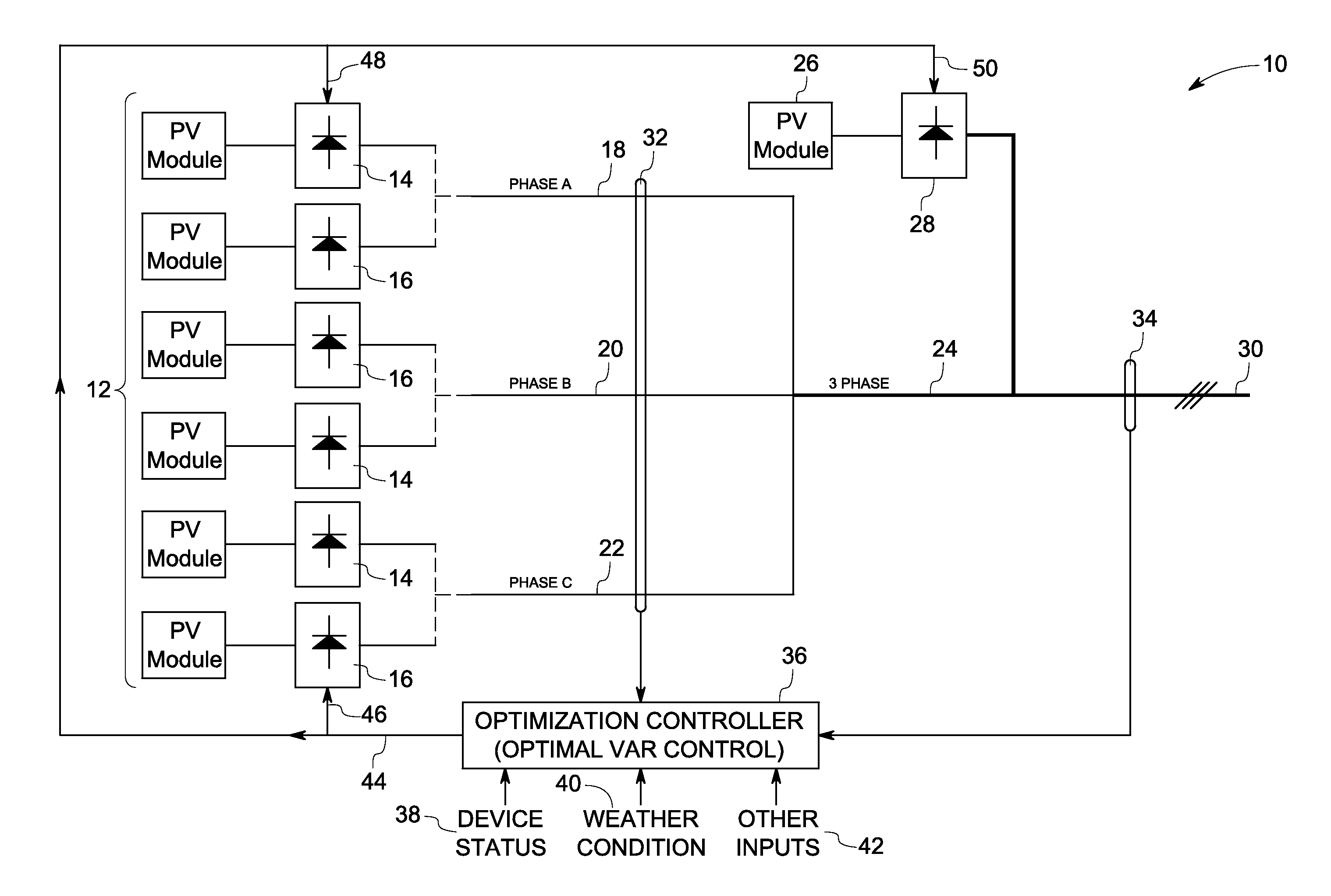
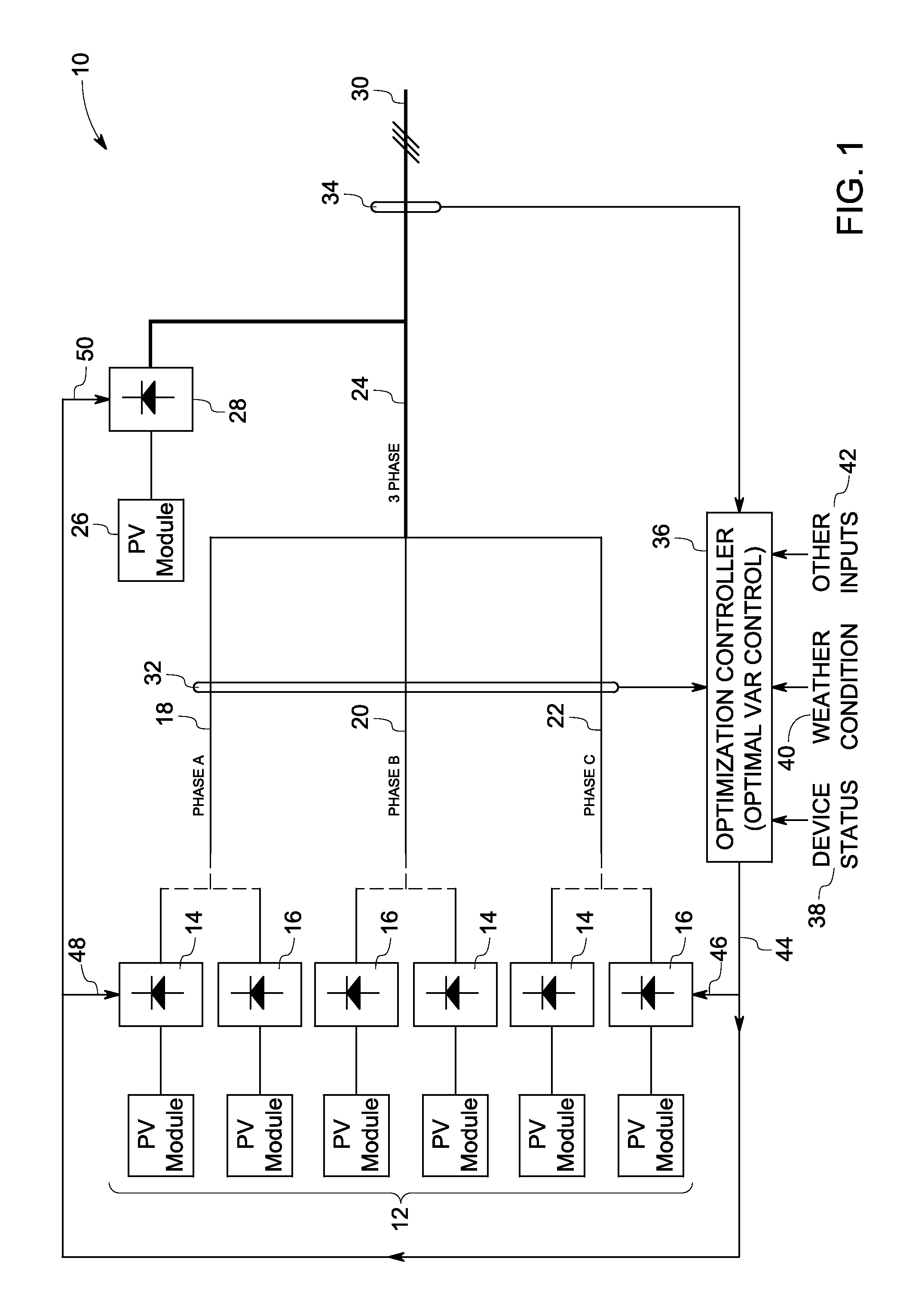
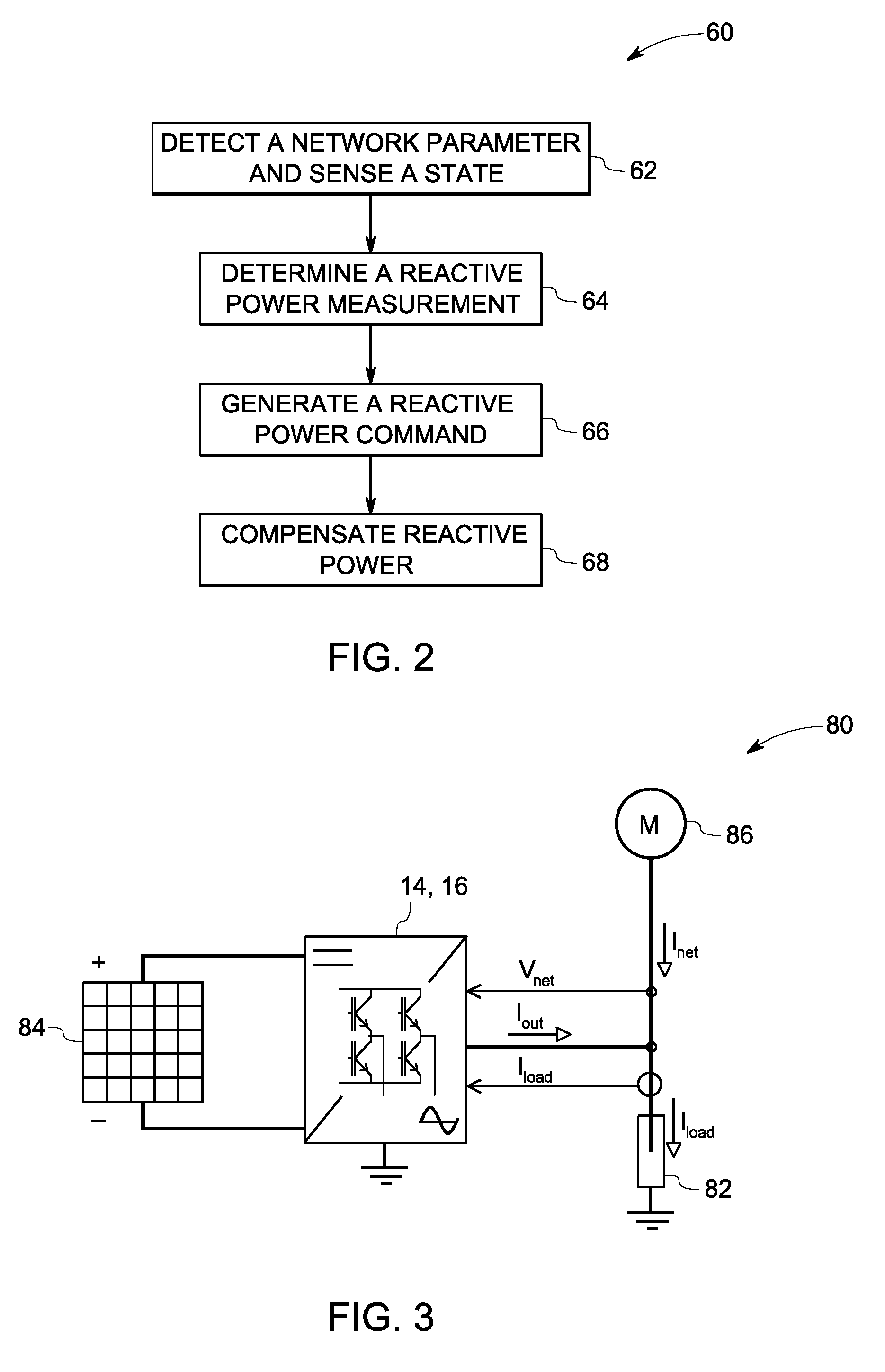
A method of providing reactive power support is proposed. The method includes detecting at least one of a plurality of network parameters in a distributed solar power generation system. The generation system includes a plurality of photovoltaic modules coupled to a grid via inverters. The method further includes sensing a state of the photovoltaic modules coupled to the distributed solar power generation system and determining a reactive power measure based upon the sensed state and the detected network parameters. The reactive power measure is used to generate a reactive power command. The reactive power command is further used to compensate reactive power in the distributed solar power generation system.

Description

BACKGROUND[0001]Embodiments of the invention generally relate to a method and system for compensating reactive power in power systems and in particular, to a method and system for compensating reactive power in solar power generation systems.[0002]Power transmission and distribution grids transmit electrical energy from generating facilities to end users. Voltage management on a transmission and distribution system is one of the factors considered for the stable operation and design of the system. Reactive power flow may be influenced by the generator source, changes in the transmission and distribution system, the addition of shunt reactive elements, and loads, for example.[0003]Reactive power is important from a standpoint of power delivery. In a typical power system reactive power flow has an influence on voltage. Since most transmission systems are inductive, increasing a reactive current component (i.e., capacitive volt-amperes reactive or VARs) will cause the voltage to rise. ...

Claims


Application Information

Patent Timeline
IPC IPC(8): H02M7/44
CPCH02J3/18H02J3/383Y02E40/30Y02E10/563H02J3/16H02J3/381H02J2300/24H02J2300/10Y02E10/56H02J3/1842Y02E40/20
Inventor GARCES, LUIS JOSELIU, YANDEROOIJ, MICHAELBOSE, SUMIT
Owner GENERAL ELECTRIC CO
Learn More