Image forming apparatus and method

a technology of image forming and forming apparatus, which is applied in the direction of printing, other printing apparatus, etc., can solve the problems of inability to achieve sufficient beneficial effects, and inability to achieve satisfactory control, etc., to reduce the visibility of banding and reduce the concentration of load

Inactive Publication Date: 2010-03-25
FUJIFILM CORP
View PDF4 Cites 2 Cited by
  • Summary
  • Abstract
  • Description
  • Claims
  • Application Information

AI Technical Summary

Benefits of technology

[0008]The present invention has been contrived in view of the foregoing circumstances, an object thereof being to provide an image forming apparatus and an image forming method whereby high-quality images can be formed by effectively reducing the visibility of banding caused by abnormal nozzles, while reducing concentration of load on particular nozzles.
[0010]According to this aspect of the present invention, if either one of the large nozzles or one of the small nozzles is an abnormal nozzle, then the dot data is corrected by using one of the other of the large nozzles and the small nozzles as a corrective nozzle, in such a manner that droplet ejection performed by the corrective nozzle substitutes for droplet ejection that is originally to be performed by the abnormal nozzle. Therefore, even in a region where the droplet ejection rate (the number of droplets ejected per unit surface area) of either the large nozzle or the small nozzle is high, a nozzle having a low droplet ejection rate is selected as the corrective nozzle. Consequently, it is possible to reduce the visibility of banding caused by the abnormal nozzle while reducing the concentration of load on a particular nozzle.
[0018]According to this aspect of the present invention, it is possible to effectively reduce the visibility of banding caused by the abnormal nozzle, in accordance with the relative amount of displacement between the first and second nozzle rows.
[0020]According to this aspect of the present invention, it is possible to make the density at a banding position caused by the abnormal nozzle substantially the same with the density in a case where there is no abnormal nozzle.
[0022]According to this aspect of the present invention, it is possible to make the density at a banding position caused by the abnormal nozzle substantially the same with the density in a case where there is no abnormal nozzle.
[0025]According to the present invention, if either a large nozzle or a small nozzle is an abnormal nozzle, then the dot data is corrected by using the other nozzle as a corrective nozzle, in such a manner that droplet ejection by the abnormal nozzle is replaced with droplet ejection by the corrective nozzle. Therefore, even in a region where the droplet ejection rate (the number of droplets ejected per unit surface area) of either the large nozzle or the small nozzle is high, a nozzle having a low droplet ejection rate is selected as the corrective nozzle. Consequently, it is possible to reduce the visibility of banding caused by an abnormal nozzle while reducing the concentration of load on a particular nozzle.

Problems solved by technology

In a thermal jet method, which performs ejection by using heating elements, a composition including large nozzles and small nozzles is particularly beneficial, since it is difficult to achieve satisfactory control of the ejection of liquid droplets having different volumes from the same nozzle, in comparison with a piezoelectric method using piezoelectric elements as actuators.
Banding (e.g., white stripes) may occur in the recorded image due to errors in the positions and the sizes of the dots formed on the recording medium by the liquid droplets ejected from the respective nozzles.
However, these methods cannot be expected to yield sufficient beneficial effects if, for example, there are nozzles suffering ejection failure due to nozzle blockages, or other causes.
However, in this method, a burden is placed on the adjacent nozzles to which the recording data of the ejection failure nozzle is assigned, and the nozzle life is shortened.
Consequently, there are limitations on the reduction of the visibility of banding, and it is difficult to improve image quality further.

Method used


Image

  • Image forming apparatus and method
  • Image forming apparatus and method
  • Image forming apparatus and method

Examples


case 1

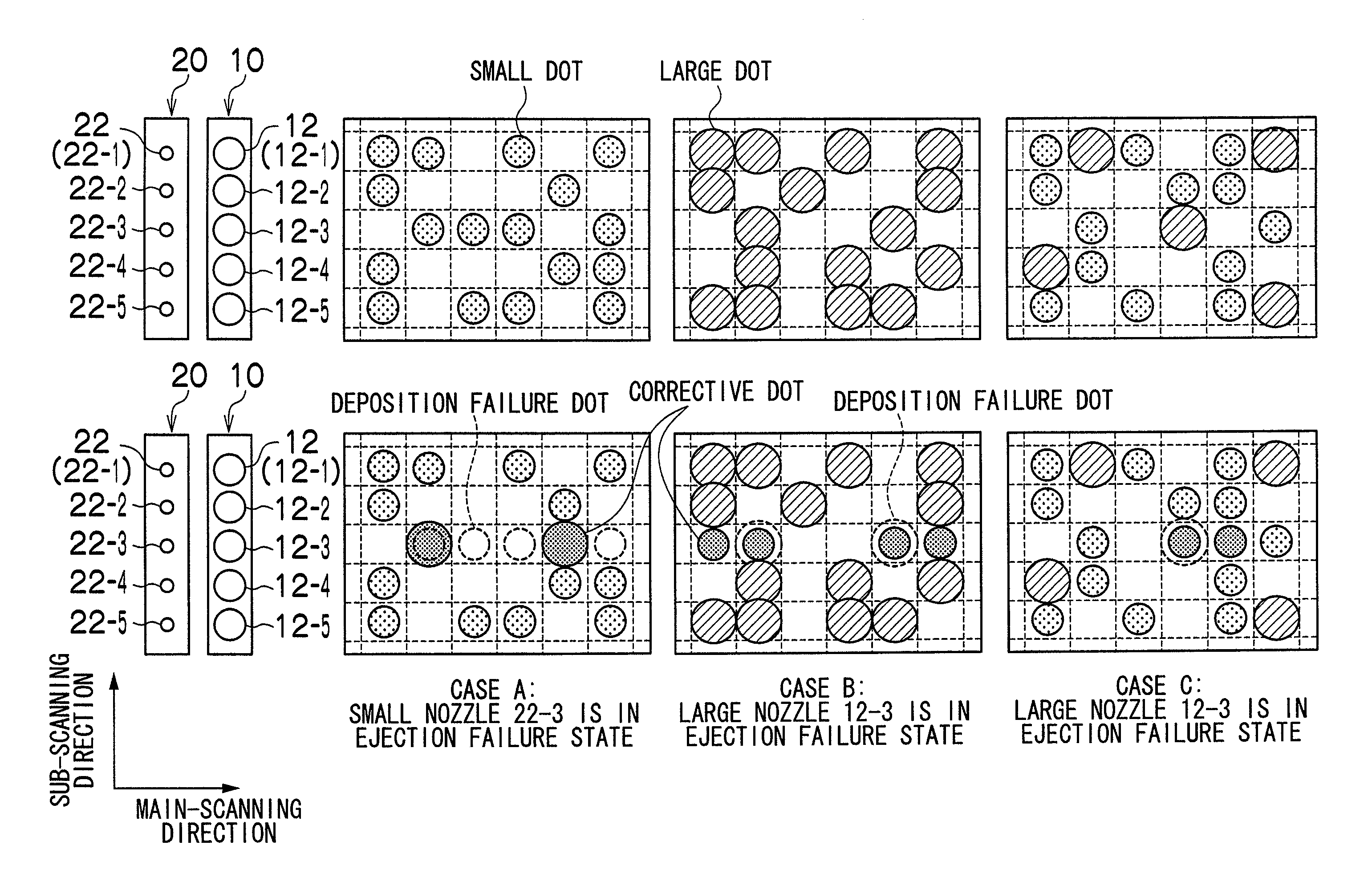
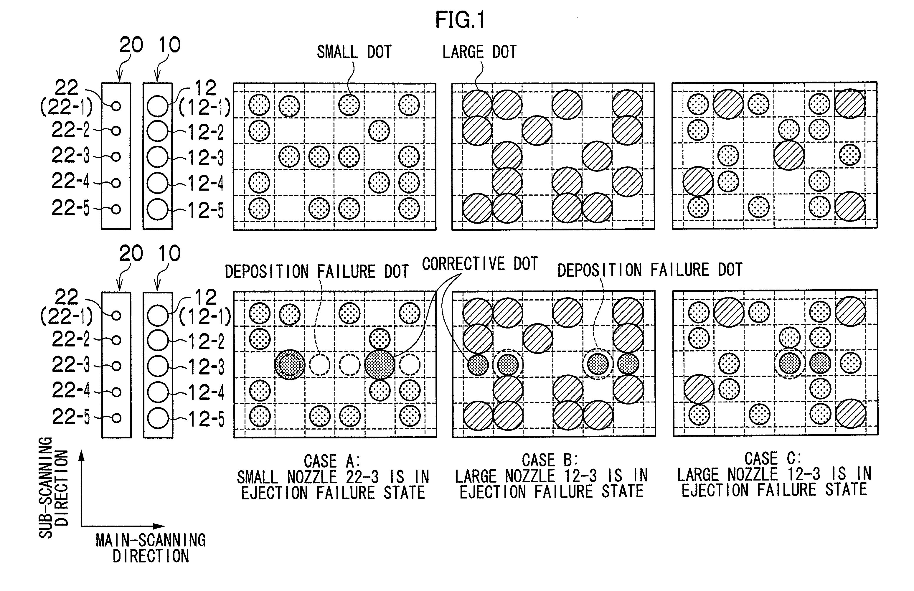
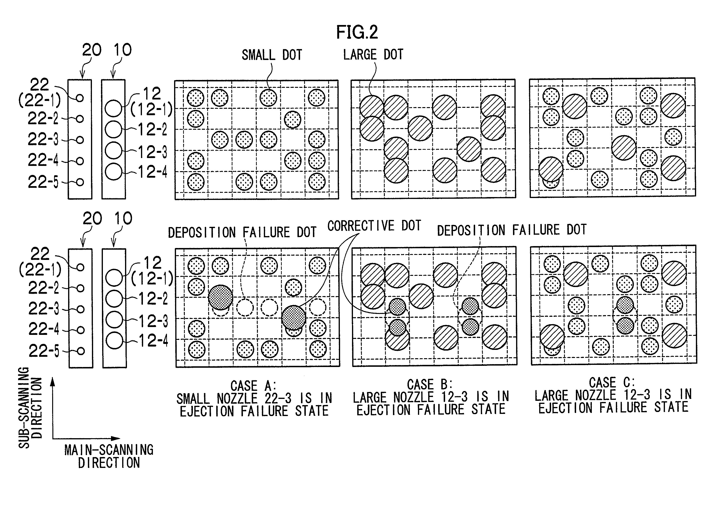
[0044](case 1) if a small nozzle is in the ejection failure state,

[0045]then one large dot substitutes for y small dots; and

case 2

[0046](case 2) if a large nozzle is in the ejection failure state,

[0047]then y small dots substitute for one large dot,

[0048]where y

[0049]This correction is desirable for the following reasons. In the case 1, if the total amount (total volume) of the liquid droplets ejected by the corrective nozzle (large nozzle) is made to be the same with the total amount of the liquid droplets that are originally to be ejected by the ejection failure nozzle (small nozzle), then although the amount of coloring material after correction becomes the same, the dot surface area after correction becomes smaller and hence the density of the corrected portion becomes lower, in comparison with the case where there is no ejection failure nozzle. Consequently, it is desirable to correct the dot data in such a manner that the total amount of the liquid droplets ejected by the corrective nozzle (large nozzle) is greater than the total amount of the liquid droplets that are originally to be ejected by the e...


PUM


Abstract

The image forming apparatus includes: a first group of large nozzles which eject large droplets of liquid for a color; a second group of small nozzles which eject small droplets of the liquid for the color, the small droplets having volume smaller than the large droplets; a dot data creation device which creates dot data according to input image data; a dot data correction device which corrects the dot data if there is an abnormal nozzle in one of the first and second groups, in such a manner that a corrective nozzle is selected from the other of the first and second groups, and droplet ejection performed by the corrective nozzle substitutes for droplet ejection that is originally to be performed by the abnormal nozzle; and a driving device which drives the large and small nozzles to eject the large and small droplets according to the corrected dot data.

Description

[0001]This application is a Divisional of co-pending application Ser. No. 11 / 714,869, filed on Mar. 7, 2007, which claims priority under 35 U.S.C. §119(a) to Patent Application No. 2006-063301 filed in Japan on Mar. 8, 2006, the entire contents of which are hereby incorporated by reference into the present application and for which priority is claimed under 35 U.S.C. §120.BACKGROUND OF THE INVENTION[0002]1. Field of the Invention[0003]The present invention relates to an image forming apparatus and an image forming method, and more particularly, to an image forming apparatus having large nozzles and small nozzles which eject liquid droplets of different volumes for the same color.[0004]2. Description of the Related Art[0005]An inkjet recording apparatus is known that is provided with large nozzles and small nozzles for ejecting droplets of liquid or ink of the same color and mutually different volumes to be deposited onto a recording medium to form high-quality images having high ton...

Claims


Application Information

Patent Timeline
Patent Type & Authority Applications(United States)
IPC IPC(8): B41J29/38
CPCB41J2/04508B41J2/0451B41J29/393B41J2/2125B41J2/2139B41J2/0458
Inventor YAMANOBE, JUN
Owner FUJIFILM CORP
Why Eureka
Try Eureka