Method of generating key code in coordinate recognition device and video device controller using the same

a technology of coordinate recognition and key code generation, which is applied in the field of video device controllers, can solve the problems of cumbersome user's repetitive operation of keypads, and achieve the effect of reducing the number of key input buttons and facilitating and accurately manipulating

Active Publication Date: 2010-03-25
LG ELECTRONICS INC
View PDF9 Cites 42 Cited by
  • Summary
  • Abstract
  • Description
  • Claims
  • Application Information

AI Technical Summary

Benefits of technology

[0007]An object of the present invention is to provide a method of generating a key code in a coordinate recognition device and a video device controller using the same, by which the number of key input buttons can be reduced.
[0008]Another object of the present invention is to provide a method of generating a key code in a coordinate recognition device and a video device controller using the same, by which the video device controller can be conveniently and accurately manipulated.
[0009]Another object of the present invention is to provide a method of generating a key code in a coordinate recognition device and a video device controller using the same, by which an object can be quickly shifted to a specific position of among OSD items displayed via a screen of the video device.
[0010]Another object of the present invention is to provide a method of generating a key code in a coordinate recognition device and a video device controller using the same, by which key codes for shifting an object displayed on an OSD menu can be generated without repetitive keypad manipulation by a user.

Problems solved by technology

This repetitious operation of the keypad is cumbersome to the user.

Method used


Image

  • Method of generating key code in coordinate recognition device and video device controller using the same
  • Method of generating key code in coordinate recognition device and video device controller using the same
  • Method of generating key code in coordinate recognition device and video device controller using the same

Examples


first embodiment

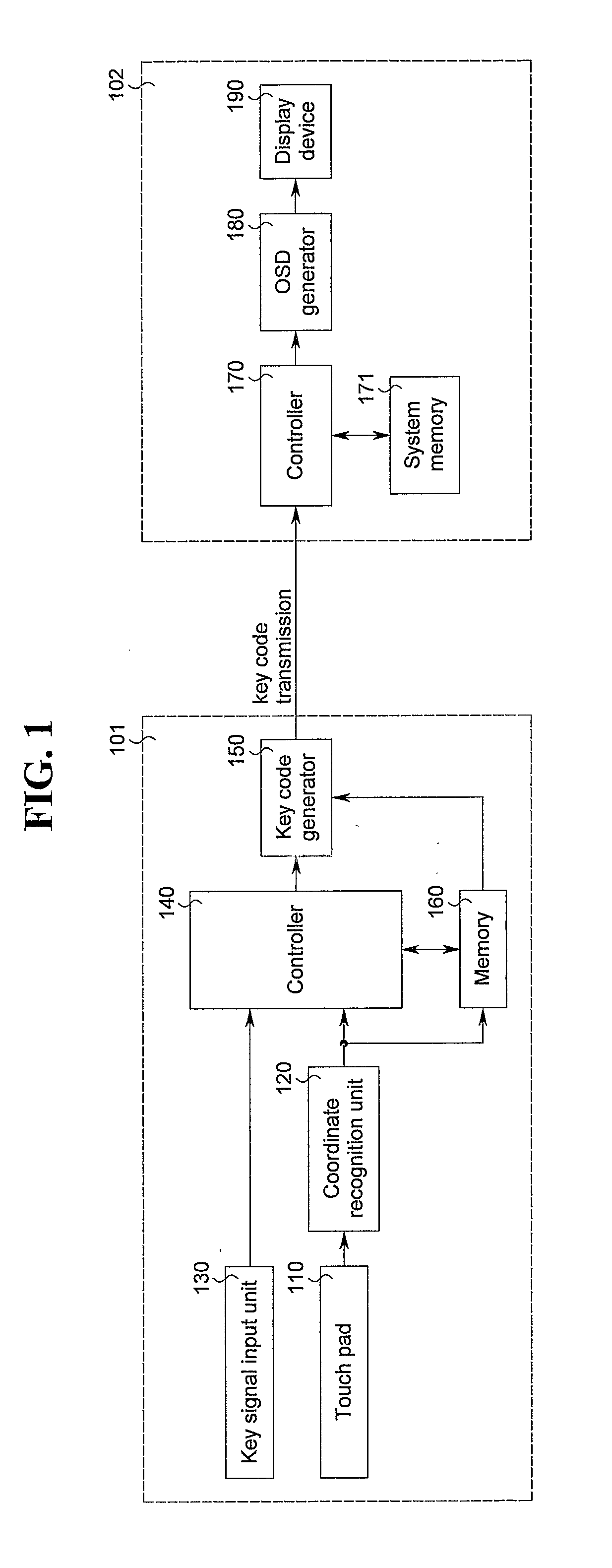
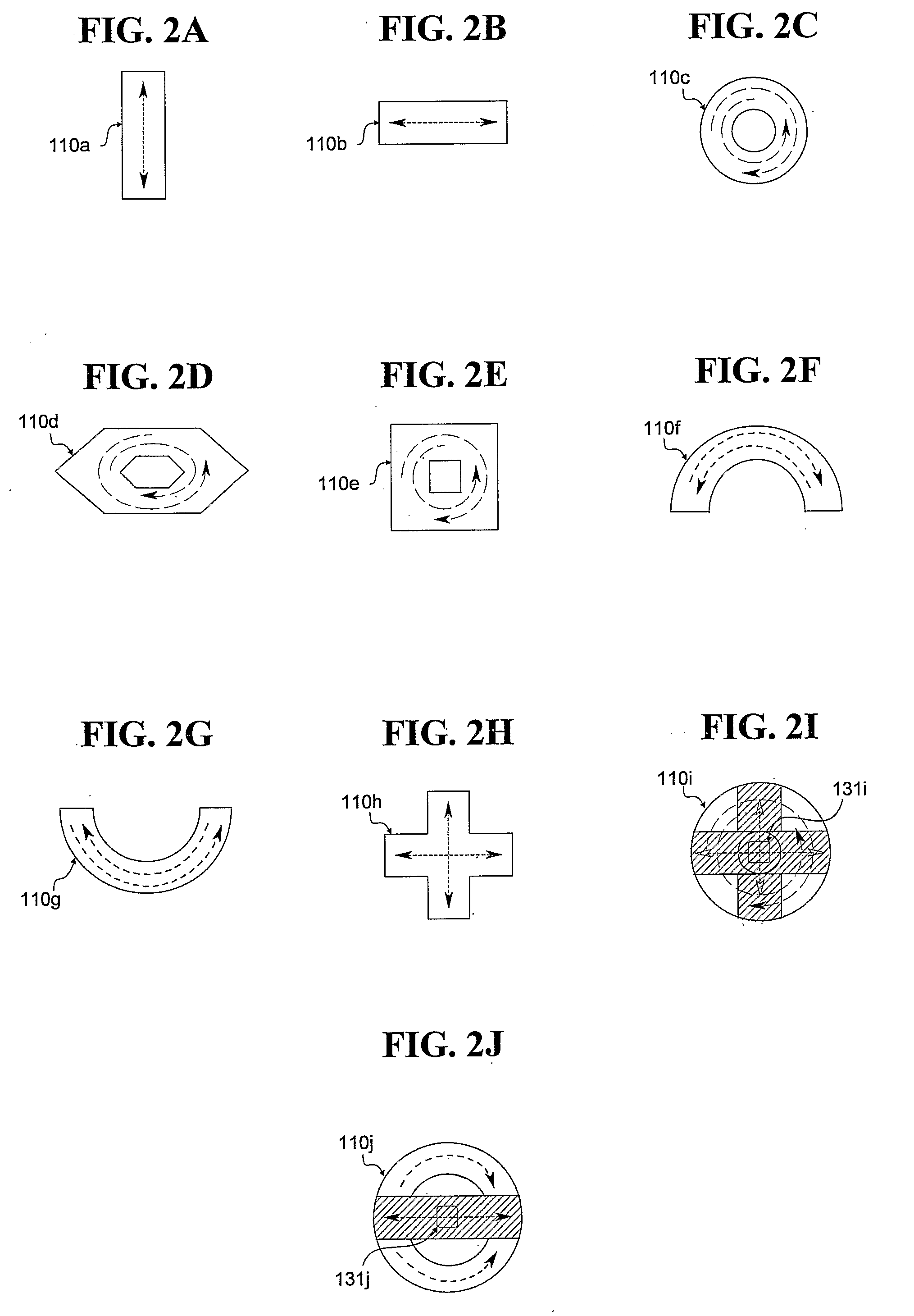
[0049]Referring to FIG. 5, illustrating a method of generating a key code in a coordinate recognition device according to the present invention, a key code is generated according to the direction, distance, and speed of a touch trajectory executed with respect to of the touch pad 110 having a predetermined touch pattern, such as the touch patterns 110a-110j. In doing so, the controller 140 first extracts start coordinates (x1, y1) and end coordinates (x2, y2), in sequence, through the coordinate recognition unit 120 in response to the touch trajectory (S401, S402), and the extracted coordinates are recognized by the coordinate recognition unit 120. Then, based on the recognized coordinate values, the controller 140 calculates a direction, distance, and speed of the touch trajectory to output a corresponding movement command signal (S403). Here, the directionality of the touch trajectory may be determined according to a process illustrated in FIGS. 6A and 6B, each showing a touch tra...

second embodiment

[0054]FIG. 7 demonstrates a method of generating a key code in a coordinate recognition device according to the present invention. As shown, a touch pattern includes a plurality touch pattern areas (focus areas), for example, first to fourth areas arranged within the touch pattern with respect to x and y axes. Here, information including one set of coordinate values corresponding to each of the arranged areas of the touch pattern are respectively stored in the memory 160 by the manufacturer, thereby enabling the controller 140 to determine touch trajectory direction, distance, and speed according to recognized coordinates of an executed touch trajectory. In particular, the stored information includes an indication of a distance between each of the plurality of touch pattern areas, which are preferably arranged such that adjacent areas are spaced equidistantly from one another.

[0055]In the example of FIG. 7, the plurality of touch pattern areas are arranged in correspondence to an an...

third embodiment

[0057]FIGS. 8A and 8B demonstrate a key code generation method according to the present invention, which assumes an annular touch pattern inherently including two y-axis areas of the touch pattern, namely, an upper y-axis area (or “Area 1”) and a lower y-axis area (or “Area 2”), which are delineated by the x axis. Here, points A-D are shown for reference purposes only. That is, the two y-axis areas of FIG. 8A are shown in FIG. 8B, in which the same areas are reconfigured for point-for-point symmetry between Areas 1 and 2, centering vertically on the maximum x-coordinate value (L / 2), to thereby reposition the coordinates of the lower y-axis area. In other words, in FIG. 8A, Areas 1 and 2 correspond to the physical nature of the touch pattern, but in FIG. 8B, the lower y-axis area is repositioned such that Areas 1 and 2 both lie above the x axis theoretically and extend to twice the maximum x-coordinate value (L).

[0058]Therefore, due to the above correspondence between Areas 1 and 2, ...


PUM


Abstract

A video device controller (101) and method for generating a key code enable key code generation by a single instance of manipulation of the controller by a user The video device controller (101) includes a touch pad (110) having a predetermined touch pattern; a coordinate recognition unit (120) for recognizing coordinate values corresponding to a touch trajectory executed with respect to the touch pad (110); a key signal input unit (130), having a plurality of keys, for generating a key signal according to a user selection, the plurality of keys including at least one hotkey corresponding to a set of video device functions; a system controller (140) for generating, in response to a user operation of the hotkey, an OSD command signal for displaying an OSD keypad having a set of menu items corresponding to the video device functions, the OSD keypad being configured according to the predetermined touch pattern, for calculating values of at least one of a direction, speed, and distance of the touch trajectory using the recognized coordinate values, and for outputting a movement command signal based on the calculated values and the key signal, the movement command signal shifting an object among the OSD menu items displayed on the video device; and a key code generator (150) for respectively generating a key code corresponding to the OSD command signal and a key code corresponding to the movement command signal.

Description

TECHNICAL FIELD[0001]The present invention relates to a controller of a video device and more particularly to a method of generating a key code in a coordinate recognition device and a video device controller using the same.BACKGROUND ART[0002]The controller of a video device (e.g., a television receiver) having a video display device may be provided with a keypad including a plurality of keys for channel selection, volume adjustment, etc. Such a keypad may be provided to a remote controller for controlling a wide variety of standard television functions.[0003]To execute a specific function, a user of the video device presses (activates) a specific function key on the controller, or remote controller, which transmits to the television receiver a coded signal corresponding to the activated function. Accordingly, such a controller may be provided with numerous keys, including frequently used and infrequently used keys. Since a great number of keys tends to encumber the user, who may h...

Claims


Application Information

Patent Timeline
Patent Type & Authority Applications(United States)
IPC IPC(8): H04N5/50G06F3/041H04N5/44G06F3/033G06F3/0354G06F3/048G06F3/0488G06F3/0489H04N5/445
CPCG06F3/0202G06F3/03547G06F3/04883G06F3/0489H04N21/47217H04N5/44543H04N2005/443H04N21/4221H04N21/42224H04N5/4403H04N21/42204H04N21/47H04Q9/04H04Q9/00
Inventor LEE, JAE KYUNGHEO, JI MIN
Owner LG ELECTRONICS INC
Why Eureka
Try Eureka