Head suspension

a head suspension and suspension technology, applied in the direction of maintaining the alignment of the head carrier, recording information storage, instruments, etc., can solve the problems of deteriorating the rigidity balance and vibration characteristic of the head suspension, the adhesive will ooze and spread, and the bonding strength will not be sufficient to correctly fix the problem, so as to achieve the effect of properly maintaining the rigidity balance and vibration characteristi

Active Publication Date: 2010-03-25
NHK SPRING CO LTD
View PDF9 Cites 56 Cited by
  • Summary
  • Abstract
  • Description
  • Claims
  • Application Information

AI Technical Summary

Benefits of technology

[0015]According to this aspect of the present invention, the adhesive is applied to a gap between the piezoelectric element and the attaching part, to attach the piezoelectric element to the attaching part. The adhesive has a thixotropic characteristic and is sol when applied to the gap. Namely, the adhesive applied to the gap between the piezoelectric element and the attaching part

Problems solved by technology

An important issue for the head suspension employing the dual actuator system is how to mount the piezoelectric elements on the head suspension.
If the quantity of the adhesive applied into the gap is too small, a bonding strength will be insufficient to correctly transmit a displaceme

Method used


Image

  • Head suspension
  • Head suspension
  • Head suspension

Examples


embodiment 1

[0027]First, a head suspension of the present invention will be explained.

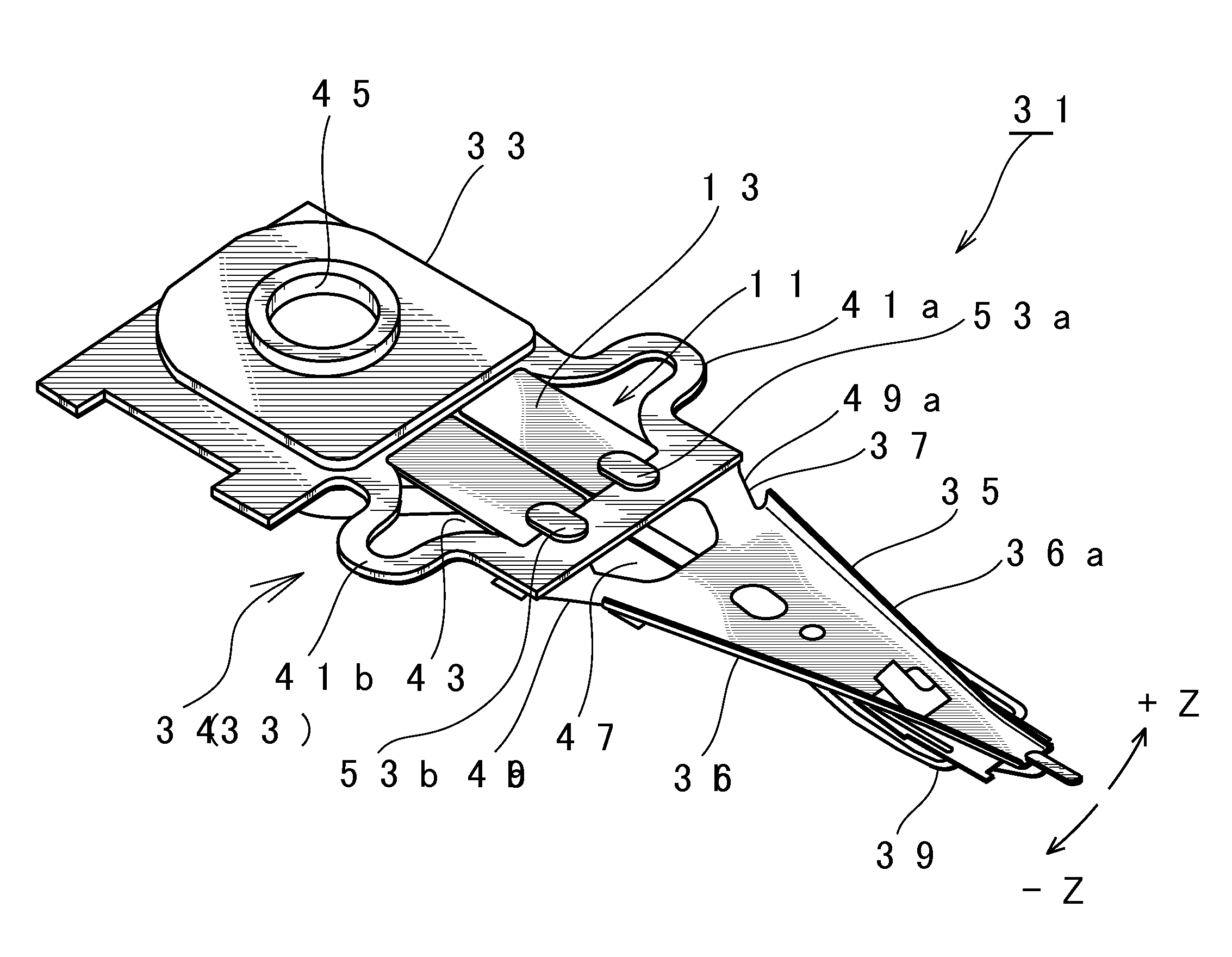
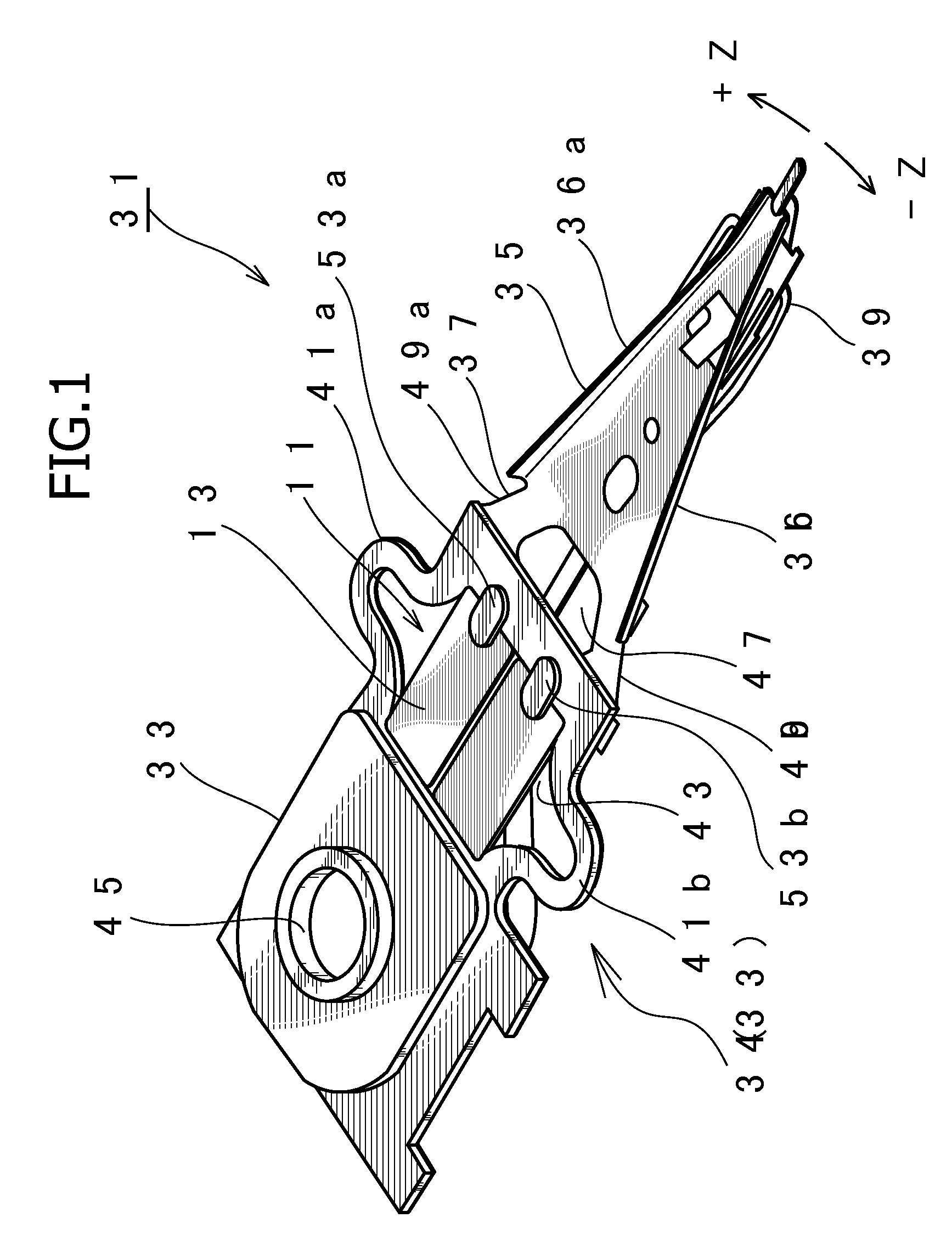
[0028]FIG. 1 is a perspective view illustrating the head suspension 31 according to Embodiment 1 of the present invention.

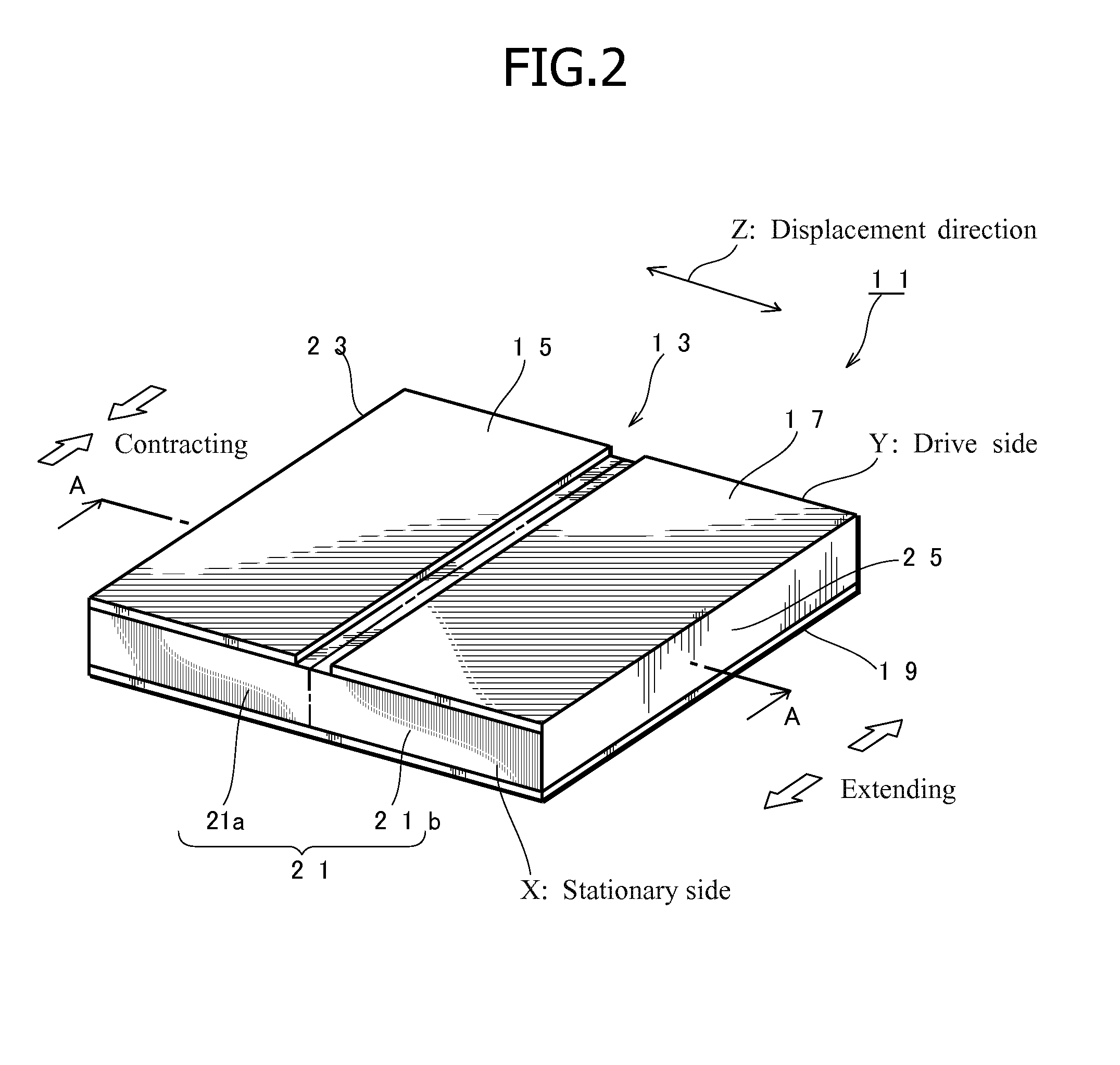
[0029]The head suspension 31 includes a piezoelectric actuator 11 consisting of a piezoelectric element 13 that deforms in response to a voltage applied thereto, a base plate 33 (corresponding to the attaching part or the base stipulated in the claims), a load beam 35, a connection plate 37 functioning as a hinge, and the like. The base plate 33 has an opening 43 in which the piezoelectric element 13 is embedded. The piezoelectric element 13 deforms in response to an applied voltage, to move a front end of the load beam 35 in a sway direction, i.e., a widthwise direction of the head suspension 31.

[0030]The base plate 33 is made of, for example, a stainless steel thin plate having a thickness of about 150 to 200 μm. The base plate 33 includes a pair of flexible parts 41a and 41b each having...

embodiment 2

[0061]A head suspension of the present invention will be explained.

[0062]FIG. 7 is a perspective view illustrating the head suspension 71 according to Embodiment 2 and FIG. 8 is a sectional view illustrating an opening 43 of the head suspension 71 over which the piezoelectric actuator 11 (FIG. 2) is arranged.

[0063]The head suspension 71 of Embodiment 2 is basically the same as the head suspension 31 of Embodiment 1, and therefore, only a difference between them will be explained.

[0064]The head suspension 71 according to Embodiment 2 includes the piezoelectric actuator 11 consisting of the piezoelectric element 13, a base plate 33 having the opening 43, and a load beam 35. The piezoelectric element 13 is arranged over the opening 43, so that a deformation of the piezoelectric element 13 moves a front end of the load beam 35 in a sway direction, i.e., a widthwise direction of the head suspension 71.

[0065]Unlike Embodiment 1 that embeds the piezoelectric element 13 in the opening 43 o...


PUM


Abstract

A head suspension has a piezoelectric element 13 that deforms in response to a voltage applied thereto, a base plate 33 provided with an opening 43 to which the piezoelectric element is attached, and a load beam 35 that is fixed to the base plate 33 so that a front end of the load beam 35 moves in a sway direction according to the deformation of the piezoelectric element 13. The head suspension includes an adhesive 51 applied to a gap 50 between the piezoelectric element 13 and the opening 43, to attach the piezoelectric element 13 to the opening 43. The adhesive 51 has a thixotropic characteristic and is sol when applied to the gap 50.
A displacement of the piezoelectric element is correctly transmitted to the load beam. The head suspension properly keeps a rigidity balance and vibration characteristic.

Description

BACKGROUND OF THE INVENTION[0001]1. Field of the Invention[0002]The present invention relates to a head suspension having a piezoelectric element that is attached to the head suspension with an adhesive and deforms in response to a voltage applied thereto.[0003]2. Description of Related Art[0004]Small-sized, precision information devices are rapidly advancing and needs for micro-actuators capable of conducting positioning control for very small distances are increasing. Such micro-actuators are highly needed by, for example, optical systems for correcting focuses and inclination angles, ink jet printers for controlling ink heads, and magnetic disk drives for controlling magnetic heads.[0005]The magnetic disk drives have an urgent issue to solve, i.e., increasing storage capacity. The storage capacity of a magnetic disk drive will increase if the storage capacity of each magnetic disk contained in the magnetic disk drive increases. The storage capacity or recording density of a magne...

Claims


Application Information

Patent Timeline
IPC IPC(8): G11B21/24
CPCG11B5/4826G11B5/596G11B5/5552G11B5/4873
Inventor OKAWARA, OSAMU
Owner NHK SPRING CO LTD
Why Eureka
Try Eureka