Dual Loop Active and Passive Repeater Antenna Isolation Improvement

a repeater antenna and passive technology, applied in the field of wireless repeater technologies, can solve the problem of always straining mobile data

Inactive Publication Date: 2010-03-25
CELLYNX INC
View PDF15 Cites 26 Cited by
  • Summary
  • Abstract
  • Description
  • Claims
  • Application Information

AI Technical Summary

Benefits of technology

[0010]Various objects, features, aspects and advantages of the inventive subject matter will become more apparent from the following det

Problems solved by technology

The wireless systems that are deployed around the world for mobile telephony and mobile data will al

Method used


Image

  • Dual Loop Active and Passive Repeater Antenna Isolation Improvement
  • Dual Loop Active and Passive Repeater Antenna Isolation Improvement

Examples


Embodiment Construction

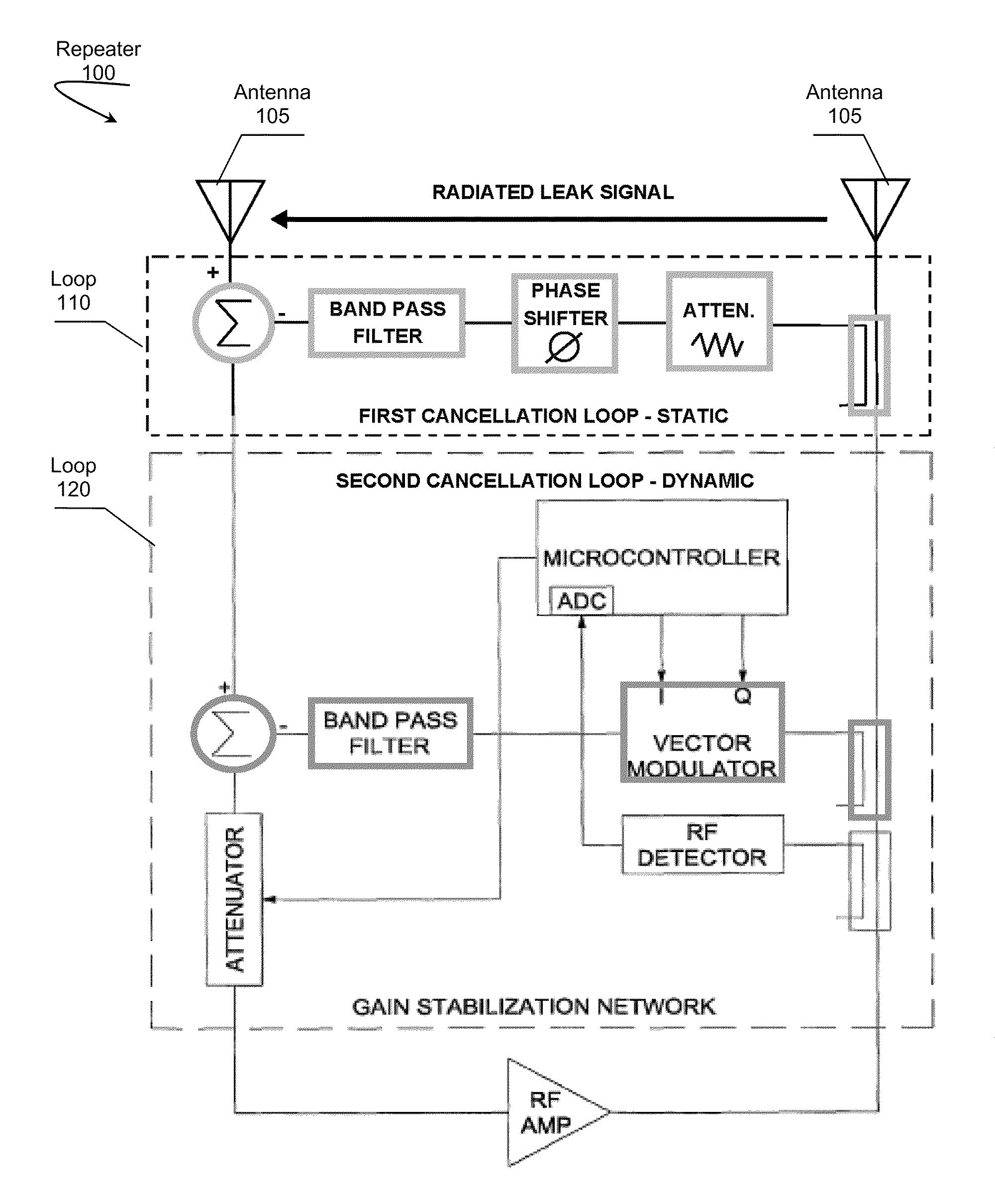
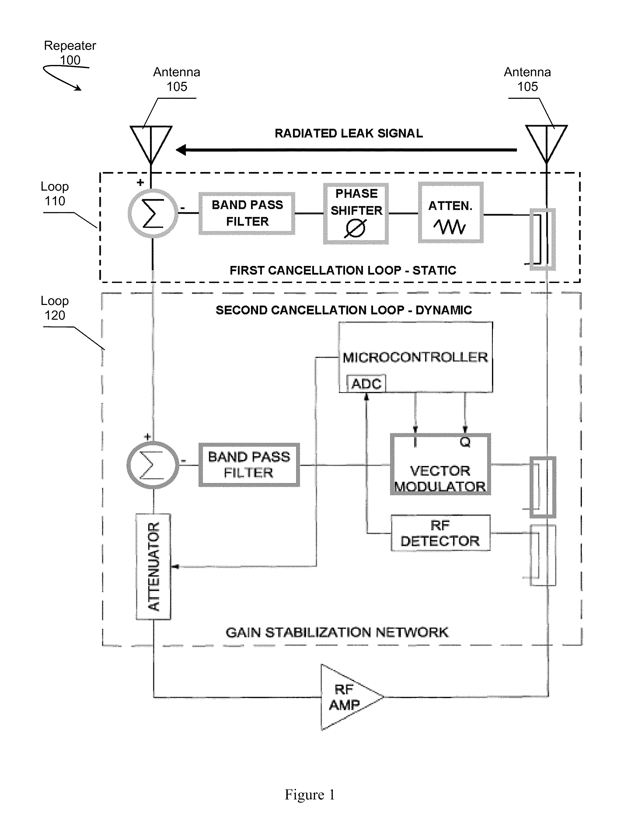
[0012]In FIG. 1, repeater 100 represents one possible embodiment of a dual loop repeater having at least two antennas 105 and comprising loop 110 configured to cancel a feedback due to a design / manufacture signal leakage, and loop 120 configured to cancel environment induced signal reflections. Loop 110 is preferably adapted to have a static configuration that does not change in real time. Loop 120 is preferably adapted to be dynamic, and to respond in real-time to changes in signal reflections, or other undesirable signals, in a deployed environment.

[0013]Various embodiments of the disclosed inventive subject matter can provide at least adequate performance of a wireless repeater with realistic antenna isolation, achieved with antennas placed very close to the bi-directional amplifier to eliminate the requirement for an installation of antennas with the spacing required with legacy repeaters.

[0014]One aspect of the inventive subject matter involves cost effectively eliminating adve...


PUM


Abstract

A wireless repeater having dual cancellation loops is presented. A first cancellation loop is configured to remove an undesirable signal resulting from a design or manufacture of the repeater. A second cancellation is configured remove undesirable signals cause by a real-time changing environment where the repeater is deployed.

Description

[0001]This application claims priority to provisional application 61 / 045662, filed Apr. 17, 2008 incorporated herein by reference in its entirety. This and all other extrinsic materials discussed herein are incorporated by reference in their entirety. Where a definition or use of a term in an incorporated reference is inconsistent or contrary to the definition of that term provided herein, the definition of that term provided herein applies and the definition of that term in the reference does not apply.FIELD OF THE INVENTION[0002]The field of the invention is wireless repeater technologies.BACKGROUND[0003]The wireless systems that are deployed around the world for mobile telephony and mobile data will always be strained to deliver adequate service in all places users desire to have the wireless service.[0004]A technique to improve the wireless service in a desired location that is autonomous to the wireless network called over-the-air repeater has been around since the beginning of...

Claims


Application Information

Patent Timeline
IPC IPC(8): H04B7/15
CPCH04B7/15571H04B1/525
Inventor DEMARCO, ANTHONYASH, DANIEL RAY
Owner CELLYNX INC
Why Eureka
Try Eureka