Optical tool with dynamic electromagnetic radiation and a system and method for determining the position and/or motion of an optical tool

a technology of dynamic electromagnetic radiation and optical tools, which is applied in the direction of speed measurement using gyroscopic effects, instruments, material analysis, etc., can solve the problems of inability to detect the position of a tool in three rotational degrees of freedom, conventional systems generally provide a relatively limited amount of information regarding the position, and conventional systems may not enable the detection of an accurate three-dimensional position of a tool

Inactive Publication Date: 2008-08-07
FLATFROG LAB
View PDF52 Cites 71 Cited by
  • Summary
  • Abstract
  • Description
  • Claims
  • Application Information

AI Technical Summary

Benefits of technology

[0012]The determined information related to the position of the tool may further be implemented to determine information related to the motion of tool as the user interacts with it. For example, determinations of position may be aggregated to determine time derivatives of the position of the tool such as velocity, acceleration, jerk, etc. These time derivat

Problems solved by technology

However, existing systems generally provide a relatively limited amount of information regarding the position of an emitting tool.
Generally, the detection of an accurate three-dimensional position of a tool is

Method used


Image

  • Optical tool with dynamic electromagnetic radiation and a system and method for determining the position and/or motion of an optical tool
  • Optical tool with dynamic electromagnetic radiation and a system and method for determining the position and/or motion of an optical tool
  • Optical tool with dynamic electromagnetic radiation and a system and method for determining the position and/or motion of an optical tool

Examples


Embodiment Construction

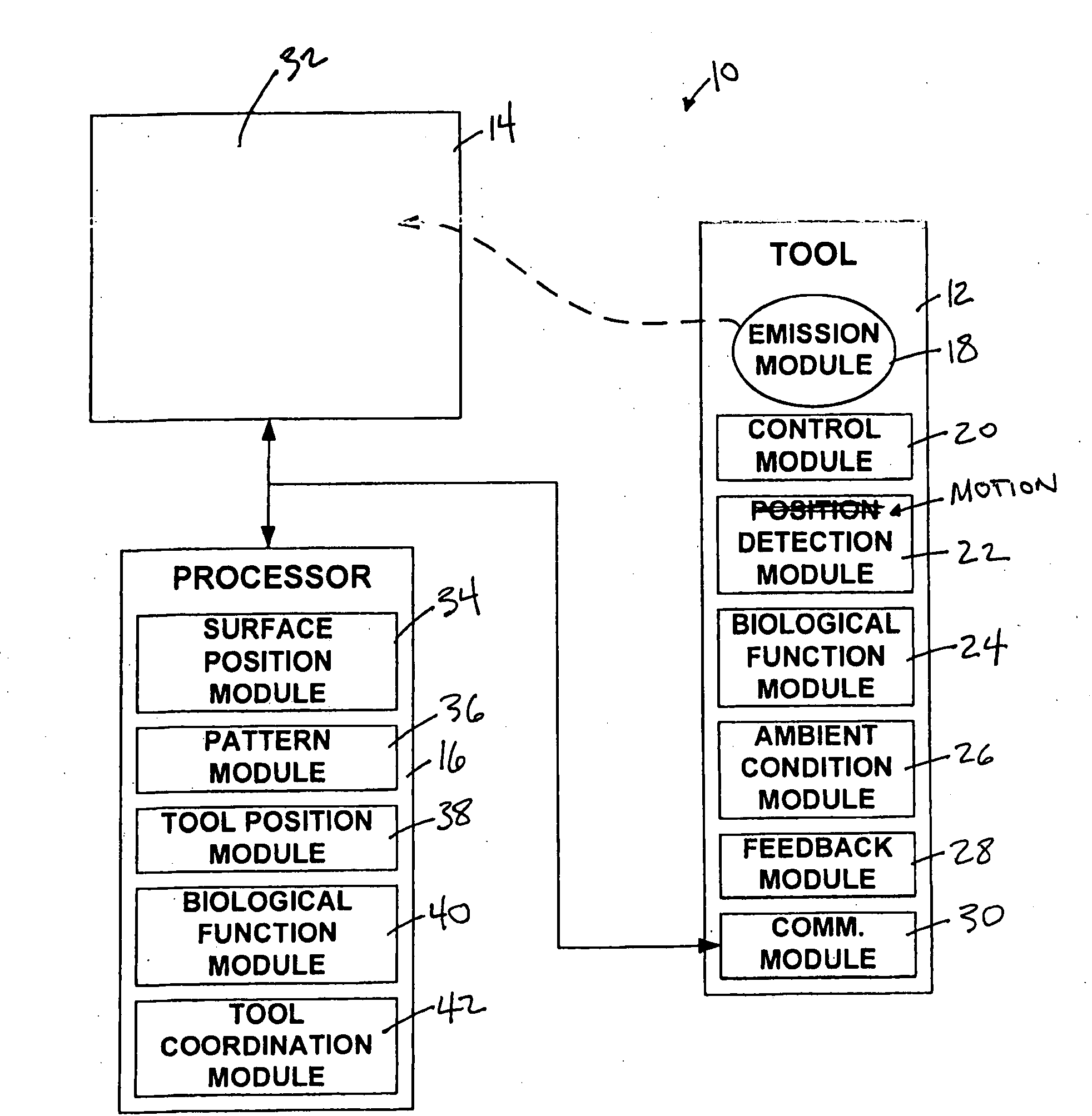
[0018]FIG. 1 illustrates an input system 10 that enables a user to input information to an electronic system in communication with input system 10, in accordance with one or more embodiments of the invention. System 10 may include a tool 12, a detection arrangement 14, a processor 16, and / or other components. The user may interact with tool 12 (e.g., hold tool 12 and position and / or move tool 12 in relation to other components of system 10) to input information to input system 10. In some implementations, tool 12 may emit electromagnetic radiation therefrom. Detection arrangement 14 may receive at least a portion of the electromagnetic radiation emitted by tool 12, and may generate one or more output signals based on one or more properties of the received electromagnetic radiation. Processor 16 may receive the one or more output signals generated by detection arrangement 14, and based at least in part on the one or more output signals may determine information related to the positio...


PUM


Abstract

A tool configured to emit electromagnetic radiation therefrom such that one or more aspects of the emission of the electromagnetic radiation may be varied as a function of time. By varying the emission of the electromagnetic radiation as a function of time, the tool may enable information related to its position and/or motion to be determined with an enhanced specificity based on detection of the emitted electromagnetic radiation. For example, the varying emission of the electromagnetic radiation may enable a three dimensional position of the tool to be determined, may enable the position of the tool to be determined in three rotational degrees of freedom, and/or may enable time derivatives of these (and other) position information to be determined to quantify motion of the tool. In some implementations, the emission of the electromagnetic radiation may be varied such that position and/or motion information related to a plurality of tools may be determined simultaneously (or substantially simultaneously).

Description

FIELD OF THE INVENTION[0001]The invention relates to tools that emit electromagnetic radiation to enable the detection of information related to the position and / or motion of the tools, and to systems and methods for determining information related to the position and / or motion of tools that emit electromagnetic radiation.BACKGROUND OF THE INVENTION[0002]The implementation of tools that emit (or otherwise interact with) electromagnetic radiation with detection system capable of determining information related to the position of such tools is known. However, existing systems generally provide a relatively limited amount of information regarding the position of an emitting tool. For example, a system may only determine a location at which the tool is pointed. As another example, a system may only determine a location of a tool if the tool is at or near an interface surface associated with the tool. Generally, the detection of an accurate three-dimensional position of a tool is not ena...

Claims


Application Information

Patent Timeline
IPC IPC(8): G01B11/14G01C19/00G01N33/48
CPCG06F3/0428G01B11/002
Inventor ELIASSON, JONAS OVE PHILIPLARSEN, NIELS AGERSNAPBASTUE, JENSOSTERGAARD, JENS WAGENBLAST STUBBE
Owner FLATFROG LAB
Why Eureka
Try Eureka