

Custom PSFs Using Clustered Light Sources
- Summary
- Abstract
- Description
- Claims
- Application Information
AI Technical Summary
Benefits of technology
Problems solved by technology
Method used
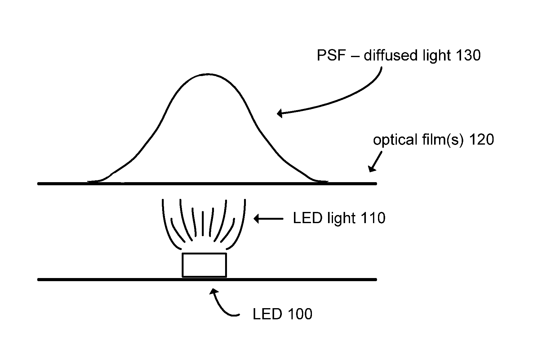
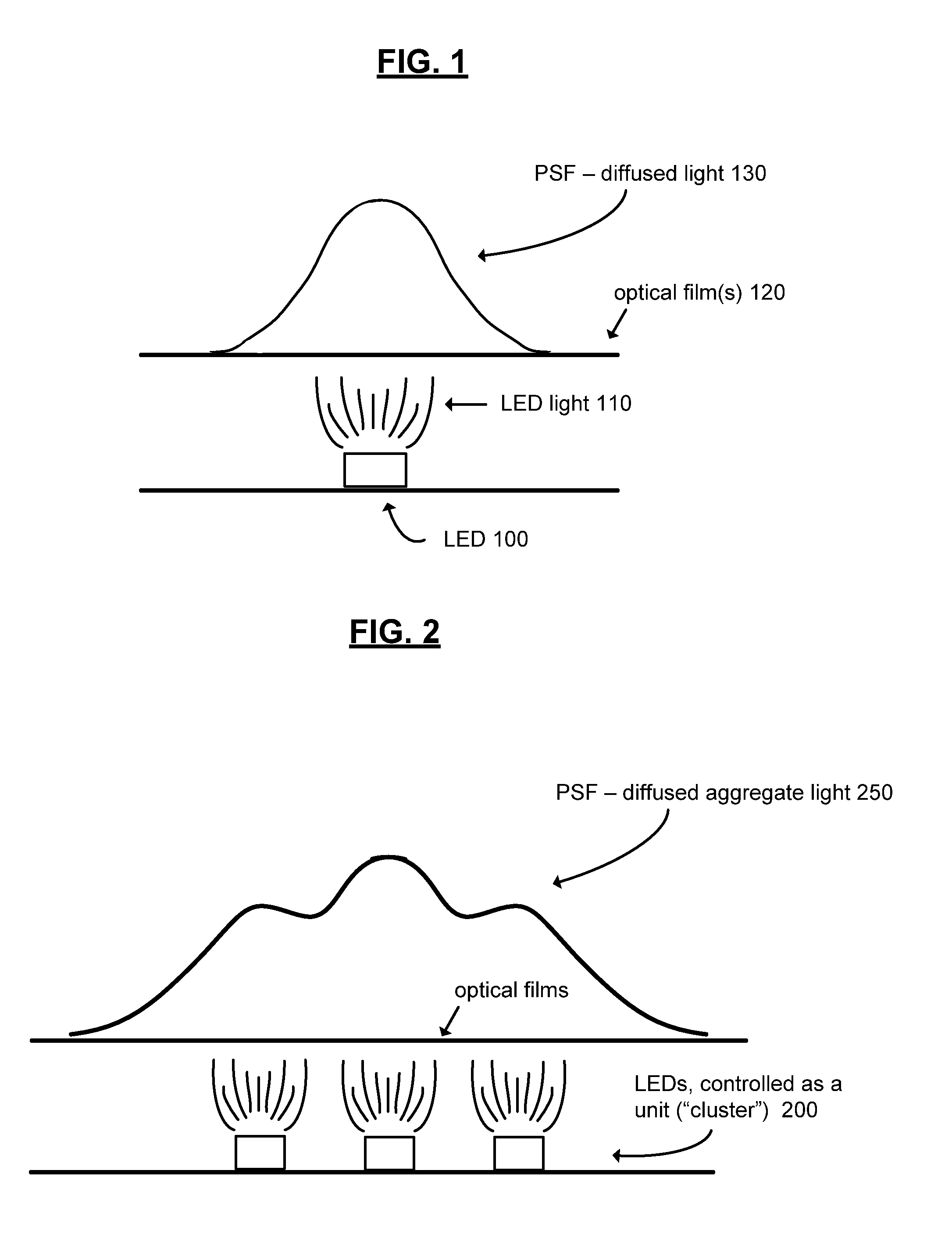
Image

Examples
Embodiment Construction
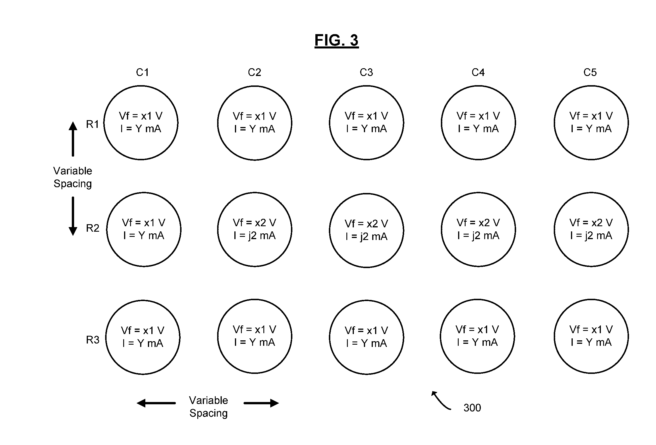
[0027]Referring again to the drawings, wherein like reference numerals designate identical or corresponding parts, and more particularly to FIG. 3 thereof, there is illustrated a schematic of an arrangement of LEDs in a cluster 300 according to an embodiment of the present invention. The cluster 300 is an exemplary cluster according to an embodiment of the present invention and comprises a 3×5 array of LEDs (e.g., LED R1,C1 and LED R3,C5 at opposite corners of the array). In other embodiments, specific rows and columns may not be apparent, and the clusters may take on shapes other than row by column arrays.
[0028]The LEDs within the cluster may be energized at variable levels. For example, in the exemplary embodiment, LEDs R2,C2 / C3 / C4 / C5 are each shown as being energized at Vf=x2 V, I=j2 mA; and the remaining LEDs, including R1,C1 are shown as being energized according to approximately Vf=x1 V, I=Y mA. Here “x1” and “x2” represent different voltages applied to the LEDs. The current d...
PUM
 Abstract
Description
Claims
Application Information