
Connector with tolerance module

a technology of tolerance module and connector, which is applied in the direction of coupling contact member, coupling device connection, coupling/insulating coupling contact member, etc., can solve the problem of higher tolerance requirements of connector, and achieve the effect of convenient implementation and simple structur

Active Publication Date: 2021-03-11
CHINA AVIATION OPTICAL-ELECTRICAL TECH CO LTD
View PDF27 Cites 4 Cited by
  • Summary
  • Abstract
  • Description
  • Claims
  • Application Information

AI Technical Summary

Benefits of technology

This patent describes a connector solution that allows for better tolerance between the plug and socket, resulting in improved transmission performance. The connector has a second housing that only moves in a perpendicular direction to the axial direction of the connector, reducing the displacement of different contact members. The guide columns and counterbores in the connector have a simple structure that is easy to implement.

Problems solved by technology

However, due to the influence of factors such as assembly error and product error, when two mutually adapted modules of one connector assembly are used, displacement relative to the designed position tends to occur, and the displacement includes not only the displacement in the plugging direction, but also the displacement perpendicular to the plugging direction, leading to higher requirements on the tolerance of the connector.
However, if the radio frequency coaxial connector is used as a differential connector, due to the large number of the contact members, the displacement of the second housing will drive all the second contact members to displace at the same time, and the degree of displacement of the different second contact members will be different due to the different positions of the displacement axes, which will have a large impact on the transmission performance of high-density connectors such as the differential connector.

Method used


Image

  • Connector with tolerance module
  • Connector with tolerance module
  • Connector with tolerance module

Examples


Embodiment Construction

[0049]The present invention will be further described below with reference to the drawings.

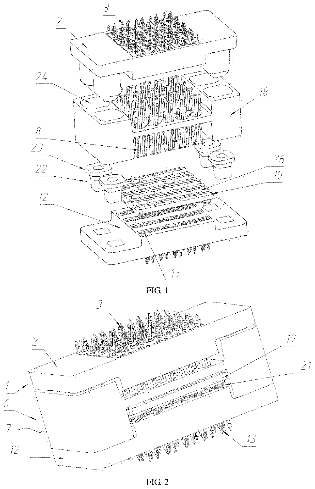
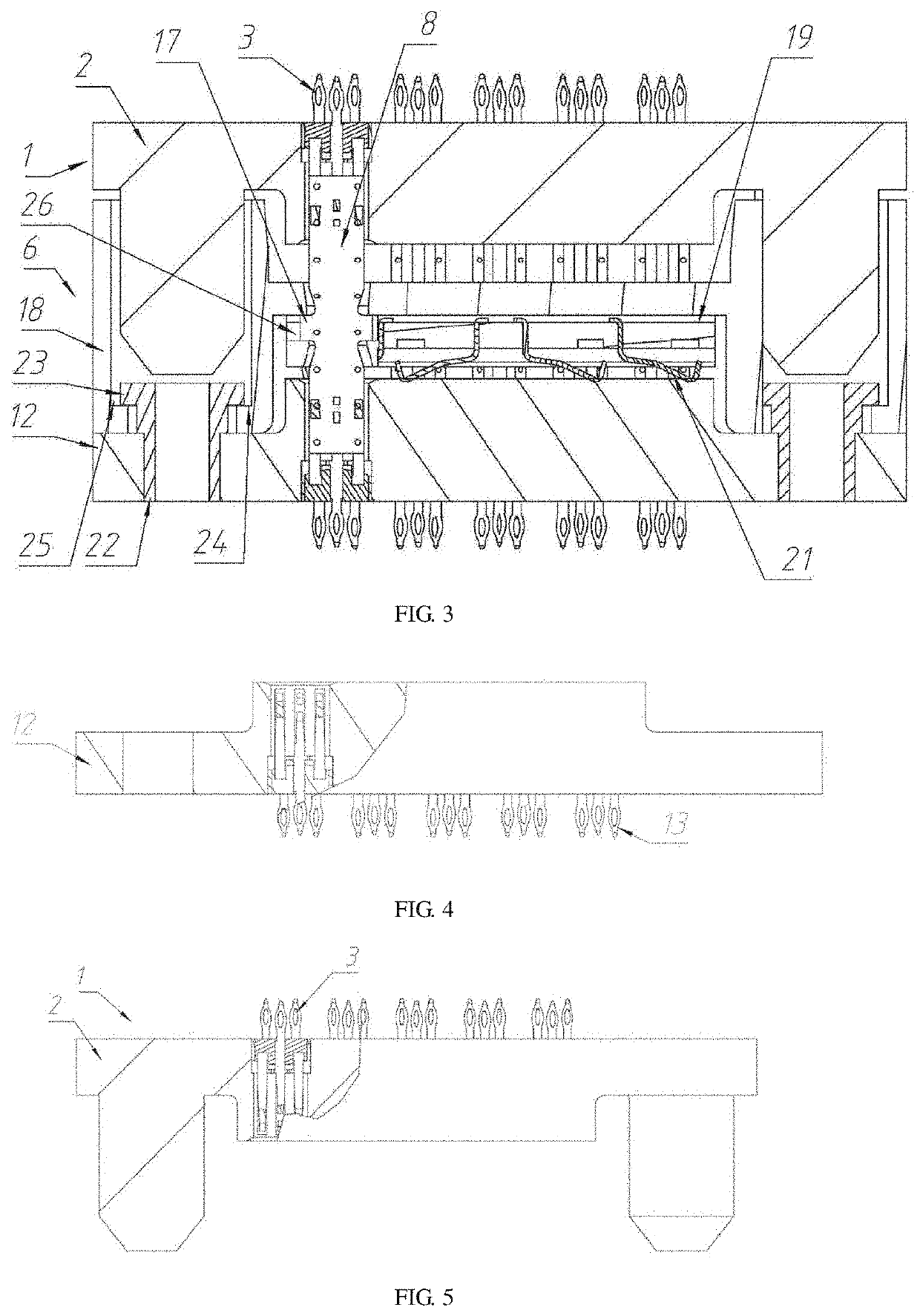
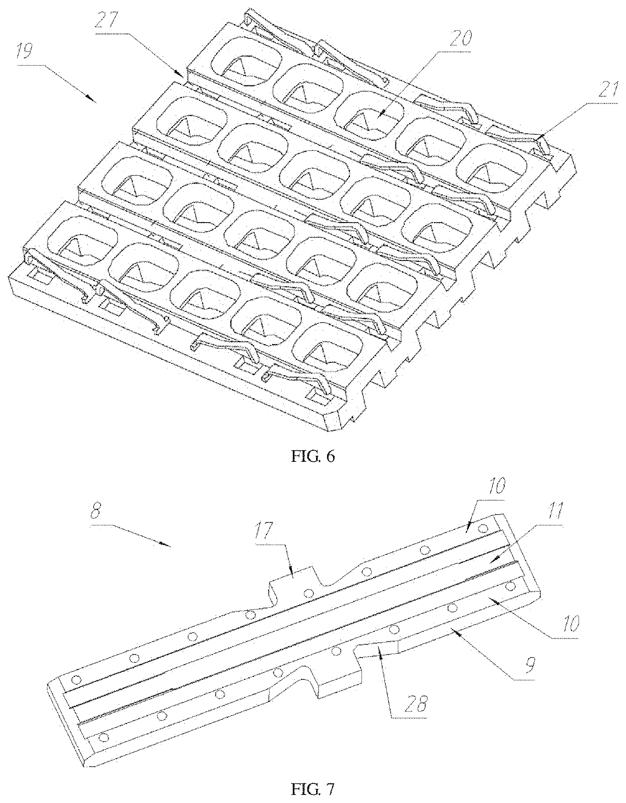
[0050]One embodiment of the connector with the tolerance module according to the present invention is shown in FIG. 1 to 12 and is a differential connector, which belongs to high-density connectors. The connector is in a two-piece structure comprising a socket 1 and a plug 6 adapted to the socket 1, wherein the socket 1 comprises a first housing 2 and first contact members 3, the plug 6 comprises a second housing 7 and a third housing 12, the second housing 7 is internally provided with second contact members 8, the third housing 12 is provided with third contact members 13, and the second housing 7 and the second contact member 8 are used for forming the tolerance module. The formed tolerance module can play a role of leverage to reduce the displacement of the plugged part, and the adopted principle exists the prior art. As shown in FIG. 8, taking a parallel board connection mode (i.e., the c...


PUM


Abstract

A connector with a tolerance module includes a socket and a plug adapted to the socket, wherein the socket includes a first housing, the plug includes a tolerance module and a third housing, the tolerance module includes a second housing, the second housing includes second contact members, the second housing is movably arranged on the third housing in a direction perpendicular to the axial direction of the connector, and the second contact members are floatingly assembled in the second housing to enable displacement in the direction perpendicular to the axial direction of the connector. The second housing only generates translational motion without displacement when the connector is inserted. The tolerance of the plug and the socket is realized by the floating assembly of the second contact members in the second housing.

Description

TECHNICAL FIELD[0001]The present invention relates to a connector with a tolerance module.BACKGROUND ART[0002]The application of connectors is common, and plays an important role on some special occasions, such as connectors adopted in CPCI (compact peripheral component interconnect) buses, new PCIE (peripheral component interconnect express) buses and ATCA (advanced telecom computing architecture) communication computing systems that are widely applied in the civilian and military fields. PCI (peripheral component interconnect) bus-based high-speed backplane connectors are mainly applied in two fields: 1. the data network field, including enterprise routers, converters, memories, servers, supercomputers, etc.; 2. the wireless communication field, including communication base stations, core routers, converters and the like. Important connectors that are widely applied in the fields above are board-to-board connectors, which are small in structure and applicable to intensive assembly...

Claims


Application Information

Patent Timeline
Patent Type & Authority Applications(United States)
IPC IPC(8): H01R12/71H01R13/46H01R13/631
CPCH01R12/716H01R13/6315H01R13/46H01R12/71H01R12/91H01R13/02H01R13/40H01R13/631H01R13/648H01R13/665H01R24/00H01R31/06H01R12/7082H01R12/73H01R12/585H01R13/6658H01R13/6471H01R12/737H05K1/14H05K1/142H05K2201/10189H05K2201/10704H05K1/115H05K1/184H05K2201/10515H05K2201/10871H05K2201/10856H05K2201/10878
Inventor YUAN, JUNFENGMA, LUFEI
Owner CHINA AVIATION OPTICAL-ELECTRICAL TECH CO LTD
Learn More