Multiple flow path microreactor design

a microreactor and flow path technology, applied in the direction of machines/engines, instruments, laboratory glassware, etc., can solve the problem that reference does not solve all the problems related to controlled and even distribution

Active Publication Date: 2010-04-01
CORNING INC
View PDF20 Cites 26 Cited by
  • Summary
  • Abstract
  • Description
  • Claims
  • Application Information

AI Technical Summary

Benefits of technology

[0016]A microfluidic device comprises at least one reactant passage (26) defined by walls and comprising at least one parallel multiple flow path configuration, said parallel multiple flow path configuration comprising a group of elementary design patterns of the flow path which are arranged in series with fluid communication so as to constitute flow paths, and in parallel so as to constitute a multiple flow path elementary design pattern in the parallel flow paths, said elementary design pattern being able to provid

Problems solved by technology

However this reference does not solve all the issues re

Method used


Image

  • Multiple flow path microreactor design
  • Multiple flow path microreactor design
  • Multiple flow path microreactor design

Examples


first embodiment

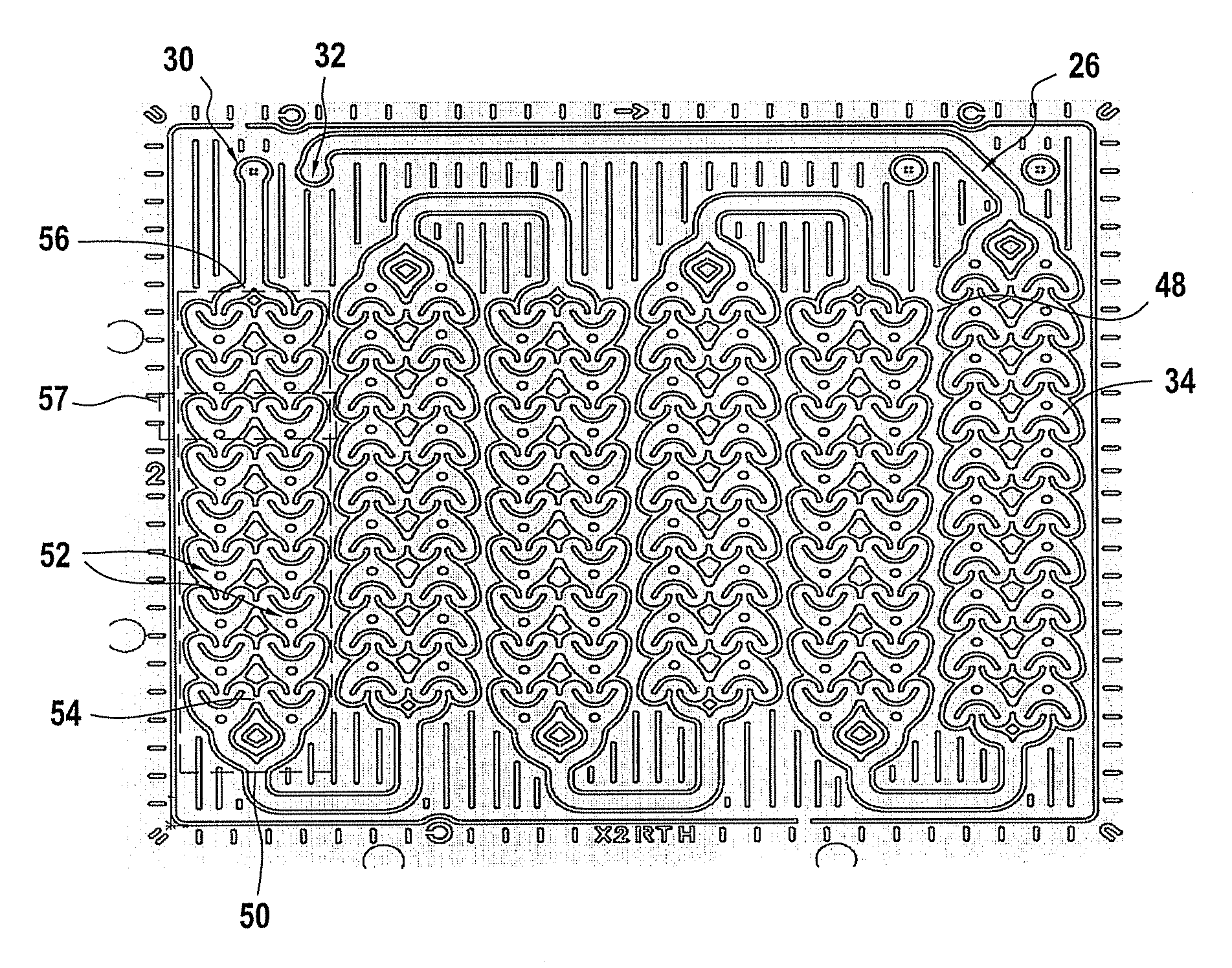
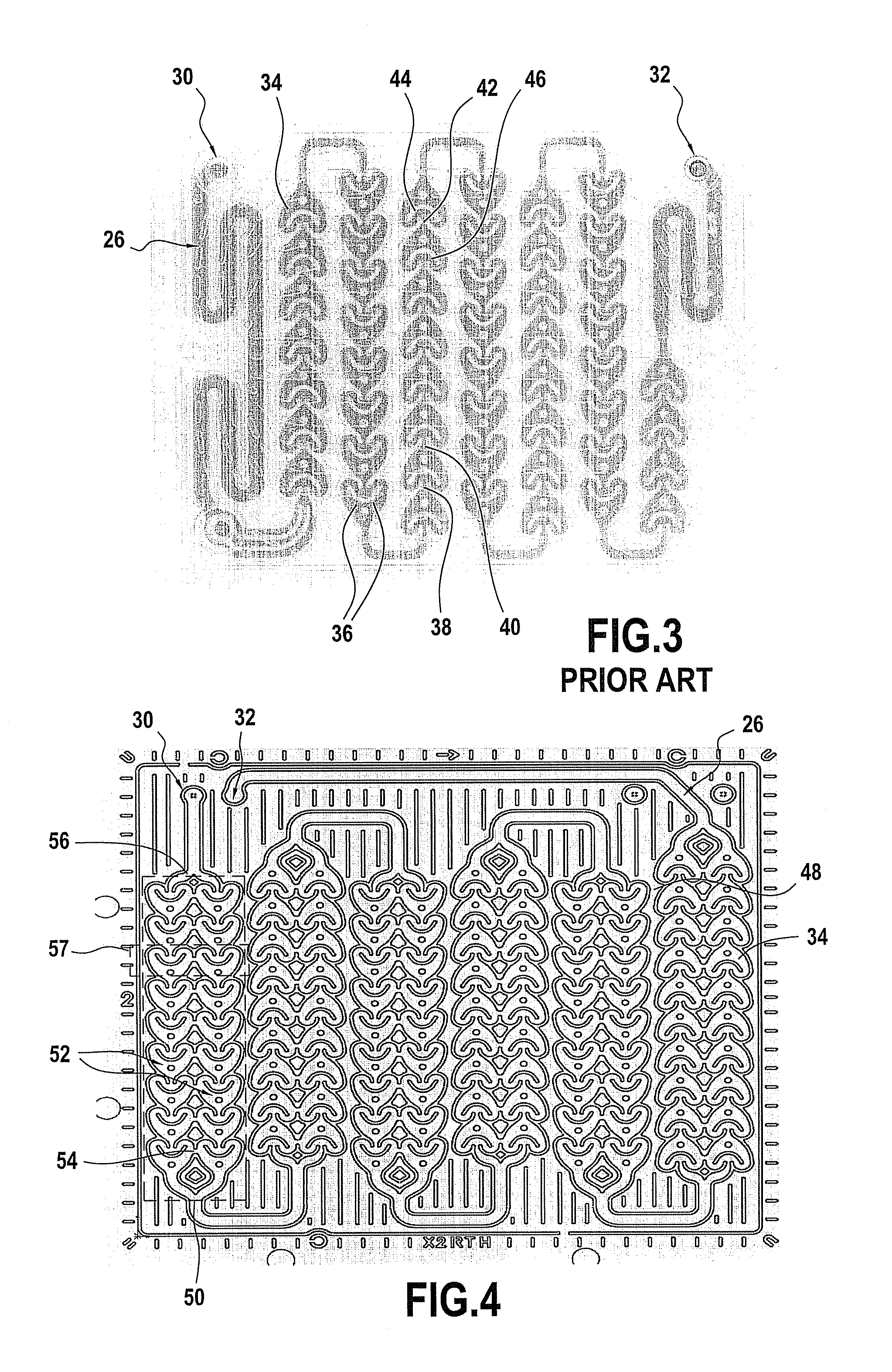
[0043]In FIG. 4 is visible a microfluidic device having a reactant passage 26 with six parallel multiple flow path configurations 50 placed in series. Each parallel multiple flow path configuration 50 has two parallel path flows 52 formed by the succession of nine chambers 34 placed in series in adjacent manner. Each chamber 34 forms an elementary design pattern of a first type, which is similar to that of FIG. 3, able to provide good mixing quality and to maintain liquid immiscible or gas liquid dispersion.

[0044]The two parallel path flows 52 are adjacent to each other. Also the adjacent chambers 34 of the two parallel path flows 52 form pairs of chambers 34 (more generally a multiple flow path elementary design pattern 57 with a communicating zone 54 between them. This communicating zone 54 is formed by a direct fluid connection between the pairs of chambers 34 so that when the flow of fluid passes in parallel in the two parallel path flows 52, there is a possible passage of flui...

second embodiment

[0081]In the alternative staggered configuration of the pillars of FIG. 13, which shows the present invention, each cross-section of the open cell 134, which is perpendicular to the fluid flow direction, contains at least one portion of pillar(s). The parallel multiple flow path configuration 150 of FIG. 13 forms an enlarged multiple fluid flow path disposed downstream a manifold 156 having a very simple configuration.

[0082]With these elementary design pattern of the second type in the form of an open cell 134 with pillars 166, sub passages of the flow path 152 are defined by the pillars 166, between the pillars 166 which are offset in the lateral direction, i.e. which are not in alignment along the flow path 152.

[0083]The elementary design pattern of the second type 134 is particularly dedicated for homogenous fluid residence time.

[0084]In FIGS. 12 and 13, there are two flow paths 152 in parallel, each multiple flow path elementary design pattern 157 having two design patterns of t...


PUM


Abstract

A microfluidic device comprises at least one reactant passage defined by walls and comprising at least one parallel multiple flow path configuration comprising a group of elementary design patterns being able to provide mixing and/or residence time which are arranged in series with fluid communication so as to constitute flow paths, and in parallel so as to constitute a multiple flow path elementary design pattern, wherein the parallel multiple flow path configuration comprises at least two communicating zones between elementary design patterns of two adjacent parallel flow paths, said communicating zones being in the same plane as that defined by said elementary design patterns between which said communicating zone is placed and allowing passage of fluid in order to minimize mass flow rate difference between adjacent parallel flow paths which have the same flow direction.

Description

PRIORITY[0001]This application claims priority to European Patent Application Number 08305711.7, filed Oct. 22, 2008 and European Patent Application Number 08305610.1 filed Sep. 29, 2008, titled “Multiple Flow Path Microreactor Design”.BACKGROUND OF THE INVENTION[0002]Microfluidic devices, as understood herein, include fluidic devices over a scale ranging from microns to a few millimeters, that is, devices with fluid channels the smallest dimension of which is in the range of microns to a few millimeters, and preferably in the range of from about 10's of microns to about 2 millimeters. Partly because of their characteristically low total process fluid volumes and characteristically high surface to volume ratios, microfluidic devices, particularly microreactors, can be useful to perform difficult, dangerous, or even otherwise impossible chemical reactions and processes in a safe, efficient, and environmentally-friendly way. Such improved chemical processing is often described as “pro...

Claims


Application Information

Patent Timeline
IPC IPC(8): G01N35/00
CPCB01F5/0603B01F5/061B01F5/0641B01F5/0646B01F5/0647B01F5/0655B01L2400/086B01F2005/0022B01F2005/0621B01F2005/0636B01L3/502746B01L2300/0816B01L2400/08B01F13/0059Y10T137/8593B01F2025/915B01F25/421B01F25/431B01F25/4317B01F25/4321B01F25/431971B01F25/4331B01F25/433B01F25/4338B01F33/30B01J19/00B01F25/20B01F25/40B01F33/00
Inventor GUIDAT, ROLANDLAVRIC, ELENA DANIELALOBET, OLIVIERWOEHL, PIERRE
Owner CORNING INC
Why Eureka
Try Eureka