Method to degrade braking modes

Active Publication Date: 2010-04-01
THE BF GOODRICH CO
View PDF6 Cites 21 Cited by
  • Summary
  • Abstract
  • Description
  • Claims
  • Application Information

AI Technical Summary

Benefits of technology

[0004]A system, apparatus and method in accordance with the present invention enables a feedback regulation scheme (also referred to as control strategy or control mode) for controlling brakes of a vehicle, such as an aircraft, to be changed based on an operational statu

Problems solved by technology

In addition, the BSCU may implement anti-skid control to pr

Method used


Image

  • Method to degrade braking modes
  • Method to degrade braking modes
  • Method to degrade braking modes

Examples


Embodiment Construction

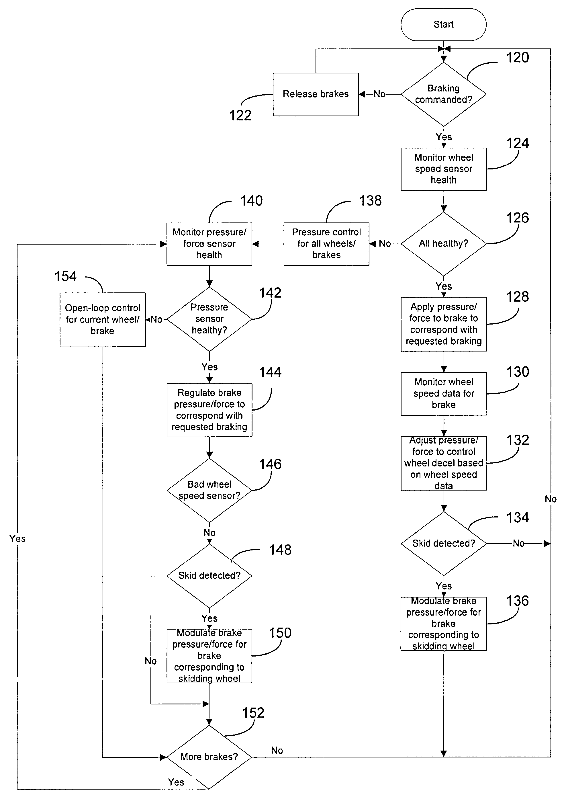
[0019]As used herein, the term “feedback regulation scheme” refers to the type of control or “control loop” utilized to command a braking force. For example, in a feedback regulation scheme that implements force control, the actual force applied by brake actuators (e.g., as measured by force sensors) may be used to close a control loop that regulates the commanded braking force (e.g., by generating a braking force command based on a reference force and a feedback force). Another example is deceleration control, wherein vehicle velocity (e.g., as measured by wheel speed sensors) is used to close the control loop to regulate a deceleration rate of the vehicle (e.g., by generating a braking force command based on a reference vehicle deceleration rate and an actual vehicle deceleration rate). Also, the term “feedback regulation scheme” includes control or control loops that do not implement feedback (e.g., open-loop control).

[0020]The principles of the invention will now be described wi...


PUM


Abstract

A system, apparatus and method of controlling a braking system of a vehicle having a plurality of rotating wheels and a plurality of brakes, each brake corresponding to one of the plurality of wheels, is provided. In controlling the brakes, an operational status of the braking system is determined. Based on the determined operational status, different feedback regulation schemes are selectively implemented to control the brake force applied by the brakes.

Description

FIELD OF THE INVENTION[0001]The present invention relates generally to brakes and, more particularly, to a method, apparatus, and system for providing brake control during failure of one or more brake components.BACKGROUND OF THE INVENTION[0002]Known in the prior art are aircraft wheel and brake assemblies including a non-rotatable wheel support, a wheel mounted to the wheel support for rotation, and a brake disk stack having front and rear axial ends and alternating rotor and stator disks mounted with respect to the wheel support and wheel for relative axial movement. Each rotor disk is coupled to the wheel for rotation therewith and each stator disk is coupled to the wheel support against rotation. A back plate is located at the rear end of the disk pack and a brake head is located at the front end. The brake head houses a plurality of actuator rams that extend to compress the brake disk stack against the back plate. Torque is taken out by the stator disks through a static torque ...

Claims


Application Information

Patent Timeline
IPC IPC(8): F16D66/00G06F17/00B60W10/18
CPCB60T2270/416B60T2270/406B60T8/885Y10T477/82B60T8/1703B60T8/17B60T8/1701B60T8/171
Inventor CAHILL, ERIC D.
Owner THE BF GOODRICH CO
Why Eureka
Try Eureka