Magnetorheological fluid compositions and prosthetic knees utilizing same

a technology of magnetorheological fluid and prosthetic knee, which is applied in the direction of magnetic bodies, other chemical processes, prostheses, etc., can solve the problems of changing frictional characteristics, difficult control, and unreliable damping performan

Active Publication Date: 2006-09-05
OSSUR HF
View PDF91 Cites 92 Cited by
  • Summary
  • Abstract
  • Description
  • Claims
  • Application Information

AI Technical Summary

Problems solved by technology

Though dry friction brakes can generally provide a substantial torque range for their size, undesirably, they are often difficult to control.
After extended use, the frictional pads tend to wear, thereby changing the frictional characteristics of the brake and the torque response for a given commanded torque.
Disadvantageously, this can cause unreliable damping performance, and hence adversely affect the gait of the amputee and also cause discomfort to the amputee.
Consequently, dry friction brakes may need frequent servicing and / or replacement which undesirably adds to the cost.
Under high loading conditions, viscous torque brakes are susceptible to leakage of hydraulic fluid and possibly other damage due to excessive pressure build-up.
Disadvantageously, this can result in an irreversible state, since once the brake unit is overloaded it cannot return to normal.
Therefore, such a viscous torque brake for a prosthetic joint is prone to catastrophic failure, and hence can be unreliable and detrimental to the safety of an amputee.
In certain MR brakes and dampers, the interaction of the MR fluid with the device causes increased pressure, seal deterioration, or a combination of the two.
Another possible cause of these adverse effects is decomposition of the MR fluid.
Once the seals fail or the MR fluid decomposes, the prosthetic knee is no longer suitable for use.

Method used


Image

  • Magnetorheological fluid compositions and prosthetic knees utilizing same
  • Magnetorheological fluid compositions and prosthetic knees utilizing same
  • Magnetorheological fluid compositions and prosthetic knees utilizing same

Examples


example 1

MR Fluid Preparation

[0053]To prepare the MR fluid, the additives were mixed with the carrier fluids and stirred. Carrier fluid was added to the iron particles and the ingredients were stirred. A Branson Digital Sonifier, Model 450, was used to disperse the iron particles in the carrier fluid. The MR fluid was then placed on the sonifier table, with the probe adjusted so that the majority of the probe was immersed in the MR fluid without touching the bottom of the mixture jar. The MR fluid was then sonicated for 1.5 minutes at 50% intensity while the sonifier table rotated. The MR fluid was checked periodically to ensure that the mixture did not become too hot. A fan was used to cool the MR fluid. Once the cycle was complete, the jar was rotated to wash down any particles that were adhered to the walls of the jar. The sonification step was then repeated two more times. Once complete, the MR fluid was removed from the sonifier and a final stir of the MR Fluid was performed to ensure t...

example 2

Prosthetic Knee MR Fluid Loading

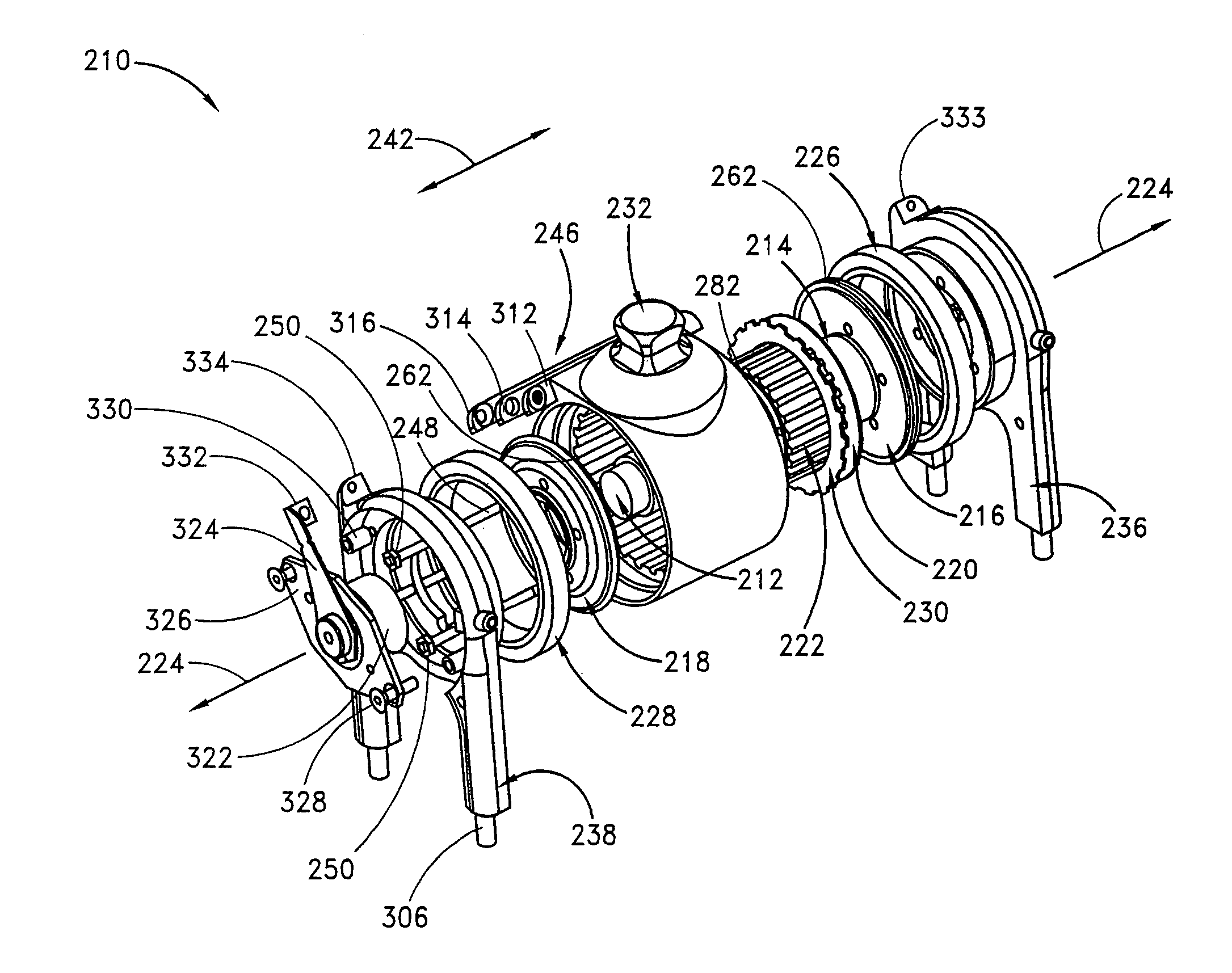
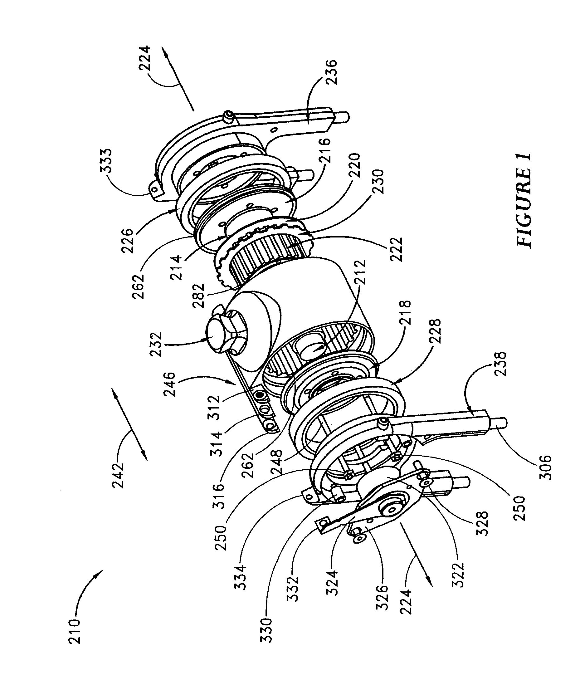
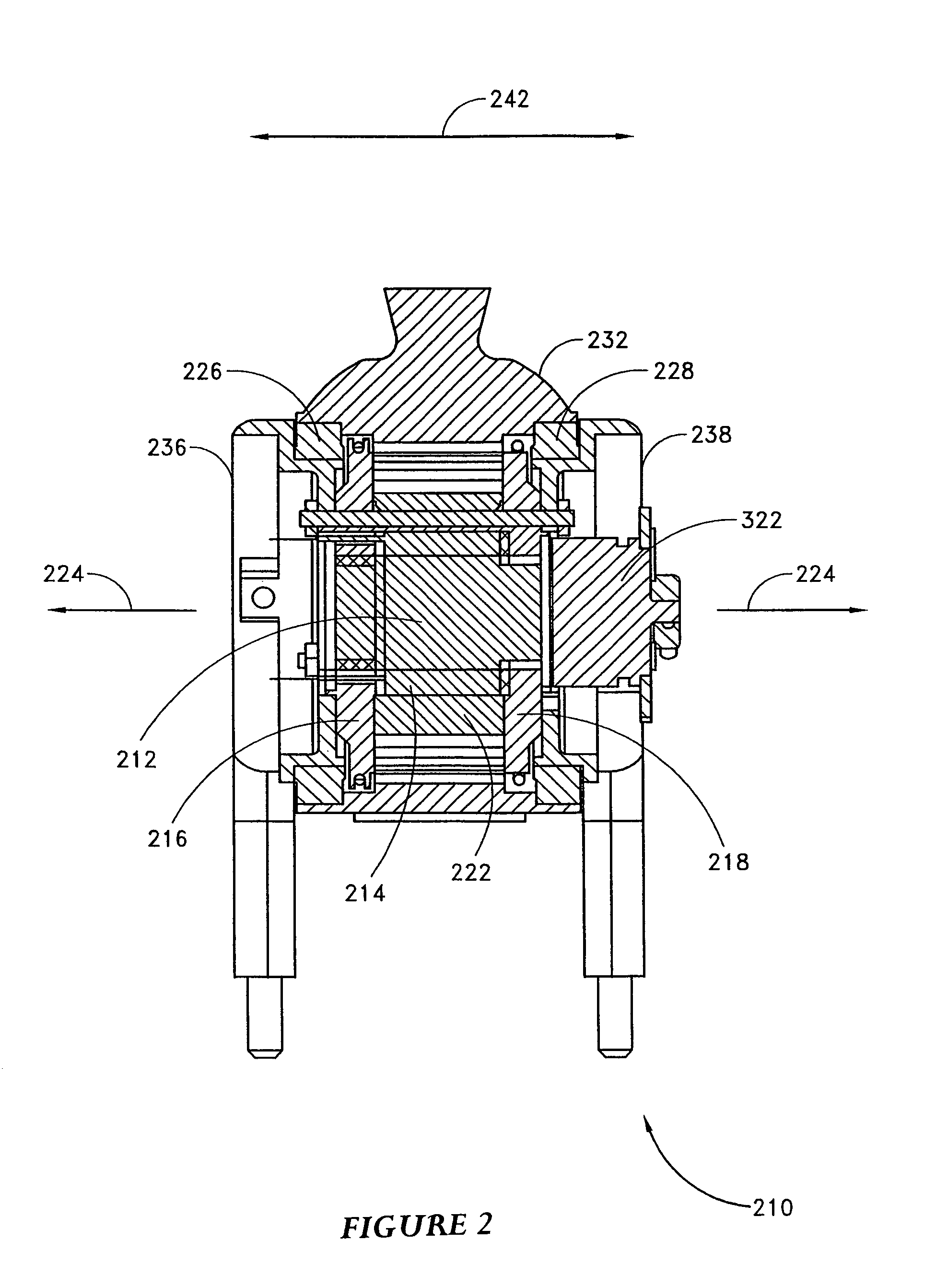
[0054]When the MR fluids as described herein are used in combination with a prosthetic knee, for example, a knee as described in U.S. Patent Publication No. 2001 / 0029400A1, certain characteristics of the fluid as well as the knee may be desired. In one embodiment, such as shown in FIGS. 4 and 5 of U.S. 2001 / 0029400A1 and FIGS. 1 and 2 disclosed herein and described in further detail below, a knee may contain a cavity or passage for holding MR fluid between a plurality of rotors and stators. The number of rotors and stators in certain embodiments may be increased or reduced in order to alter the off-state or low-end torque properties of the MR fluid used in combination with the knee. In one embodiment, the number of rotors and stators preferably range from about 50 to about 90, preferably from about 55 to about 70, but also including about 57, 59, 61, 63, 65, 67, and ranges encompassing these amounts. The knee cavity may contain a volume of about 1 to ...

example 3

MR Fluid Settling Tests

[0083]Settling tests were conducted for thirteen different MR fluids. The rate of settling varied significantly and was found to be a function of iron particle size, the use of additives, and the viscosity of the fluids.

[0084]Procedure for Settling Tests

[0085]MR fluids were formulated by adding carrier oil, with or without an additive, to a jar containing a weighed aliquot of carbonyl iron particles. For formulations containing an additive, the additive was blended with the carrier oil prior to mixing with the iron particles. The components were mixed by hand for several minutes and then the iron particles were dispersed using high frequency ultrasonic energy supplied by a Branson Digital Sonifier, Model 450. The fluids were subjected to 2–3 cycles of ultrasonic energy, each cycle having a duration of 1.5 minutes and power amplitude of approximately 50%. The fluids were then mixed again by hand to insure complete dispersion of the iron particles. Fluids were n...


PUM

PropertyMeasurementUnit
sizeaaaaaaaaaa
sizeaaaaaaaaaa
sizeaaaaaaaaaa

Abstract

The present invention relates in one embodiment to magnetorheological fluids utilized in prosthetic joints in general and, in particular, to magnetorheological fluids utilized in controllable braking systems for prosthetic knee joints. Preferred magnetorheological fluids of the present invention comprises polarizable iron particles, a carrier fluid, and optionally an additive. Preferred additives include, but are not limited to functionalized carrier fluids as well as derivatized fluoropolymers. Preferred carrier fluids include, but are not limited, to perfluorinated polyethers.

Description

RELATED APPLICATIONS DATA[0001]This application claims priority under 35 U.S.C. 119(e) from provisional application Ser. No. 60 / 467,722 filed May 2, 2003, the entirety of which is hereby incorporated by reference.BACKGROUND OF THE INVENTION[0002]1. Field of the Invention[0003]The present invention relates in one embodiment to magnetorheological fluids utilized in prosthetic joints in general and, in particular, to magnetorheological fluids utilized in controllable braking systems for prosthetic knee joints.[0004]2. Description of the Related Art[0005]Three types of variable-torque brakes have been employed in prosthetic knees in the past: (i) dry friction brakes where one material surface rubs against another surface with variable force; (ii) viscous torque brakes using hydraulic fluid squeezed through a variable sized orifice or flow restriction plate; and (iii) magnetorheological (MR) brakes or dampers where MR fluid (containing small iron particles suspended in the fluid) is sque...

Claims


Application Information

Patent Timeline
Patent Type & Authority Patents(United States)
IPC IPC(8): H01F1/44A61F2/50A61F2/68C10M171/00
CPCA61F2/68A61F2002/5004A61F2002/503A61F2002/5033A61F2002/6818C10M171/001C10M2201/05C10M2213/06C10M2213/0606H01F1/447C10N2010/14C10N2020/011C10N2020/02C10N2020/06C10N2030/02C10N2060/00C10N2060/06C10N2060/12C10N2060/09C10N2010/16
Inventor HSU, HENRYBISBEE, III, CHARLES R.PALMER, MICHAEL LARSLUKASIEWICZ, RONALD J.LINDSAY, MICHAEL W.PRINCE, STEPHEN W.
Owner OSSUR HF
Why Eureka
Try Eureka