
Brake control unit

a technology of brake control unit and control unit, which is applied in the direction of braking system, braking components, transportation and packaging, etc., can solve the problems of most current brake control unit not working properly, most systems do not have a way of notifying the operator, and most current brake control unit not efficiently operating in conjunction with a towing vehicl

Active Publication Date: 2006-09-28
HORIZON GLOBAL AMERICAS INC
View PDF70 Cites 89 Cited by
  • Summary
  • Abstract
  • Description
  • Claims
  • Application Information

AI Technical Summary

Benefits of technology

The present invention relates to a brake control unit for towed vehicles that can receive input signals from the towing vehicle, the towed vehicle, and the operator, and generate an output signal to the brakes of the towed vehicle based on these signals. The brake control unit can also store diagnostic code information and other events that will assist a service technician in diagnosing failure modes in the brake control unit or other modules with which it interfaces. Additionally, the brake control unit includes several safety features and redundant procedures built in it to protect against failures in the brake control unit, the towed vehicle, or the towing vehicle. The technical effects of the invention include improved safety and reliability of the brake control unit, as well as efficient and effective braking control for towed vehicles.

Problems solved by technology

Few, if any, of these brake control units, however, use speed inputs to provide the brake output signal.
Additionally, most current brake control units do not efficiently operate in conjunction with a towing vehicles anti-lock brake system to create a stable braking event.
On most brake control units if the main input is unavailable, the brake control unit will not function properly.
Similarly, if a short occurs in most current control brake units, the unit will either disables itself or will shut down, further causing a potentially undesirable situation.
And, if a reverse voltage is applied to most brake control units, they will be disabled.
Finally, if an error occurs in the brake control unit or between the communication of the brake control unit and the towing vehicle, most systems do not have a way of notifying the operator independent of the brake control unit or storing the error for a technician's review thereof.
They are not able to communicate with and communicate over existing systems within the towing vehicle.
For example, these units are not able to warn an operator of an error through the towing vehicle's current warning systems.
They are unable to operate with the rest of the displays on the towing vehicle's instrument panel.
Finally, most current brake control units are not effectively configurable or completely operable with a particular towing vehicle.
The brake control units are unable to be configured to respond to the idiosyncrasies of a particular vehicle, they are unable to provide diagnostic data, they are unable to adjust to conditions in the environment or in the towing vehicle, and are unable to provide life-cycle data regarding the brake control unit.

Method used


Image

  • Brake control unit
  • Brake control unit
  • Brake control unit

Examples


Embodiment Construction

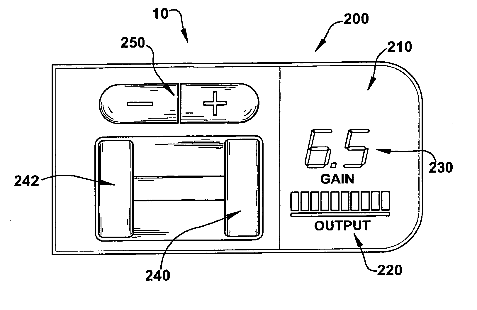
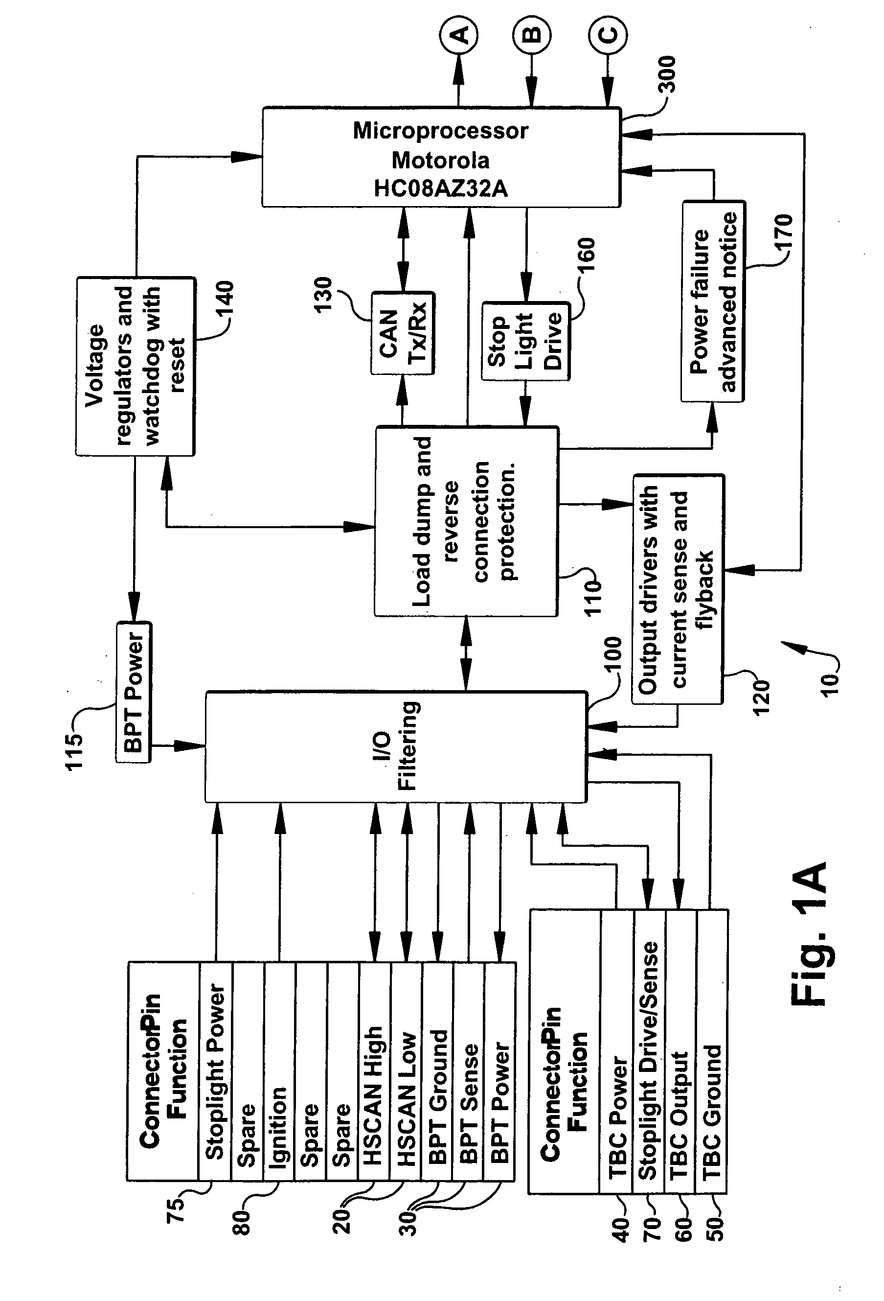
[0025] A brake control unit for a towed vehicle, e.g., a trailer, disclosed herein generates an output signal to the brakes of the towed vehicle to apply a certain brake load thereto. The output signal is related to a variety of input signals received by the brake control unit from the towing vehicle, the towed vehicle, the operator, or any combination of the three. Additionally, the brake control unit has the capability of storing diagnostic information and other events, including error events, in memory in the brake control unit. This information can assist a service technician in diagnosing failure modes in the brake control unit or other modules such as those of the towing vehicle and / or towed vehicle with which it interfaces. Further, the brake control unit has several safety / performance features and redundant procedures built in to it to protect against failures in the brake control unit, the towed vehicle, and / or the towing vehicle. Finally, the brake control unit drives the ...


PUM


Abstract

Towed vehicles can be extremely heavy. Accordingly, it is too much of a burden to the braking system of a towing vehicle to not have brakes on the towed vehicle. Controlling the brakes of the towed vehicle must be accurately applied otherwise undesirable conditions can be created. There is a need for a method for controlling braking of a towed vehicle. This method comprises receiving a first signal via a communication bus of a towing vehicle, the first signal relating to at least one operating condition of at least one the towing vehicle and a towed vehicle, sending a second signal to brakes of the towed vehicle, the second signal based on said first signal.

Description

CROSS-REFERENCE TO RELATED APPLICATIONS [0001] This application claims priority from U.S. Provisional Patent Application No. 60 / 617,062 filed on Oct. 8, 2004, and U.S. Provisional Patent Application No. 60 / 616,979 filed on Oct. 8, 2004, which are both hereby incorporated by reference.FIELD OF THE INVENTION [0002] The present invention relates generally to a brake control unit, and more specifically, to a brake control unit that provides a brake output signal to brakes of a towed vehicle based on certain inputs received. BACKGROUND OF THE INVENTION [0003] A variety of prior art brake control units that provide a brake output signal to the brakes of a towed vehicle have been proposed and / or manufactured. Few, if any, of these brake control units, however, use speed inputs to provide the brake output signal. They are mostly inertia or pressure based units. Additionally, most current brake control units do not efficiently operate in conjunction with a towing vehicles anti-lock brake sys...

Claims


Application Information

Patent Timeline
Patent Type & Authority Applications(United States)
IPC IPC(8): B60T7/20
CPCB60T7/20B60T17/22B60T8/323B60T7/085B60T8/172B60T8/885B60T2270/402B60T2270/413
Inventor ALBRIGHT, MARCIAKULKARNI, CHANDRAKUMARPRATER, JERALDREICHARD, JASONMORSE, DENNISAUSTIN, MARKBURGESS, PATHOOT, MARVINECCLESTON, LARRYZAVODNY, STEVEMARSDEN, DOUGENGLERT, KIRK
Owner HORIZON GLOBAL AMERICAS INC
Learn More