System and method for detecting, tracking and identifying a gas plume

a technology of gas plumes and systems, applied in the field of image processing, can solve problems such as difficulty in detecting their presen

Active Publication Date: 2010-04-01
BAE SYST INFORMATION & ELECTRONICS SYST INTERGRATION INC
View PDF9 Cites 19 Cited by
  • Summary
  • Abstract
  • Description
  • Claims
  • Application Information

AI Technical Summary

Benefits of technology

[0007]Another embodiment of the invention is a system for detecting and identifying a gas plume. The system comprises a processor; a detector in communication with the processor, the detector effective to scan a region of interest to detect first and second detected spectral radiance data; a database in communication with the processor, the database including a library; wherein the processor is effective to create at least a first image and a second image from the first and second detected spectral radiance data; co-register the first and second images to produce a first co-registered image and a second co-registered image; subtract the first co-registered image from the second co-registered image to produce a difference image; generate a cluster region around a difference region in the difference image; analyze the spectral radiance from the cluster region to produce a spectral characteristic curve; and correlate the spectral characteristic curve against the library to identify the gas plume.
[0008]Yet another embodiment of the invention is a method for detecting and identifying a gas plume. The method comprises receiving, by a processor, a request regarding a region of interest including a gas plume; detecting, by a detector in...

Problems solved by technology

If such gases are released in an environment, it...

Method used


Image

  • System and method for detecting, tracking and identifying a gas plume
  • System and method for detecting, tracking and identifying a gas plume
  • System and method for detecting, tracking and identifying a gas plume

Examples


Embodiment Construction

)

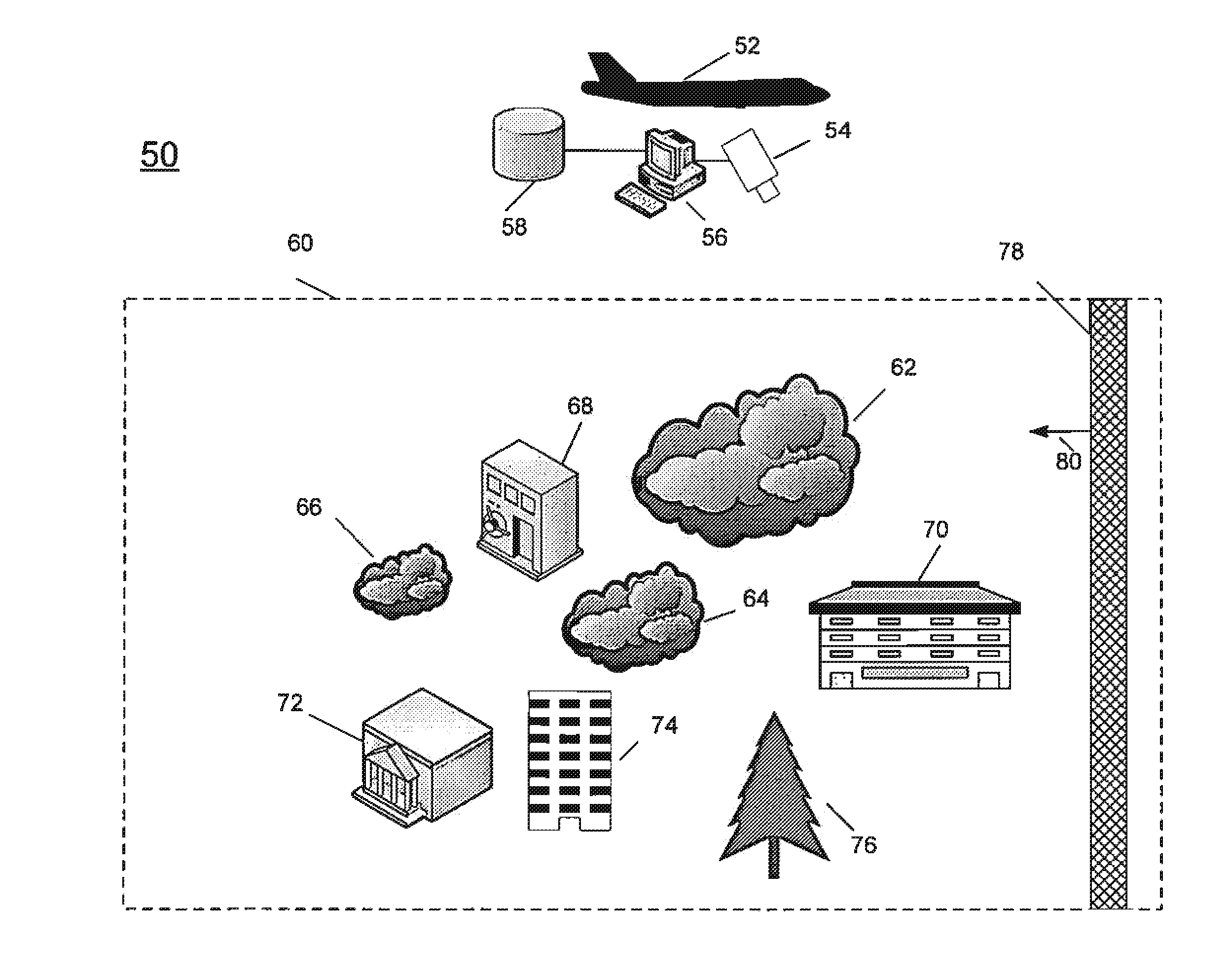
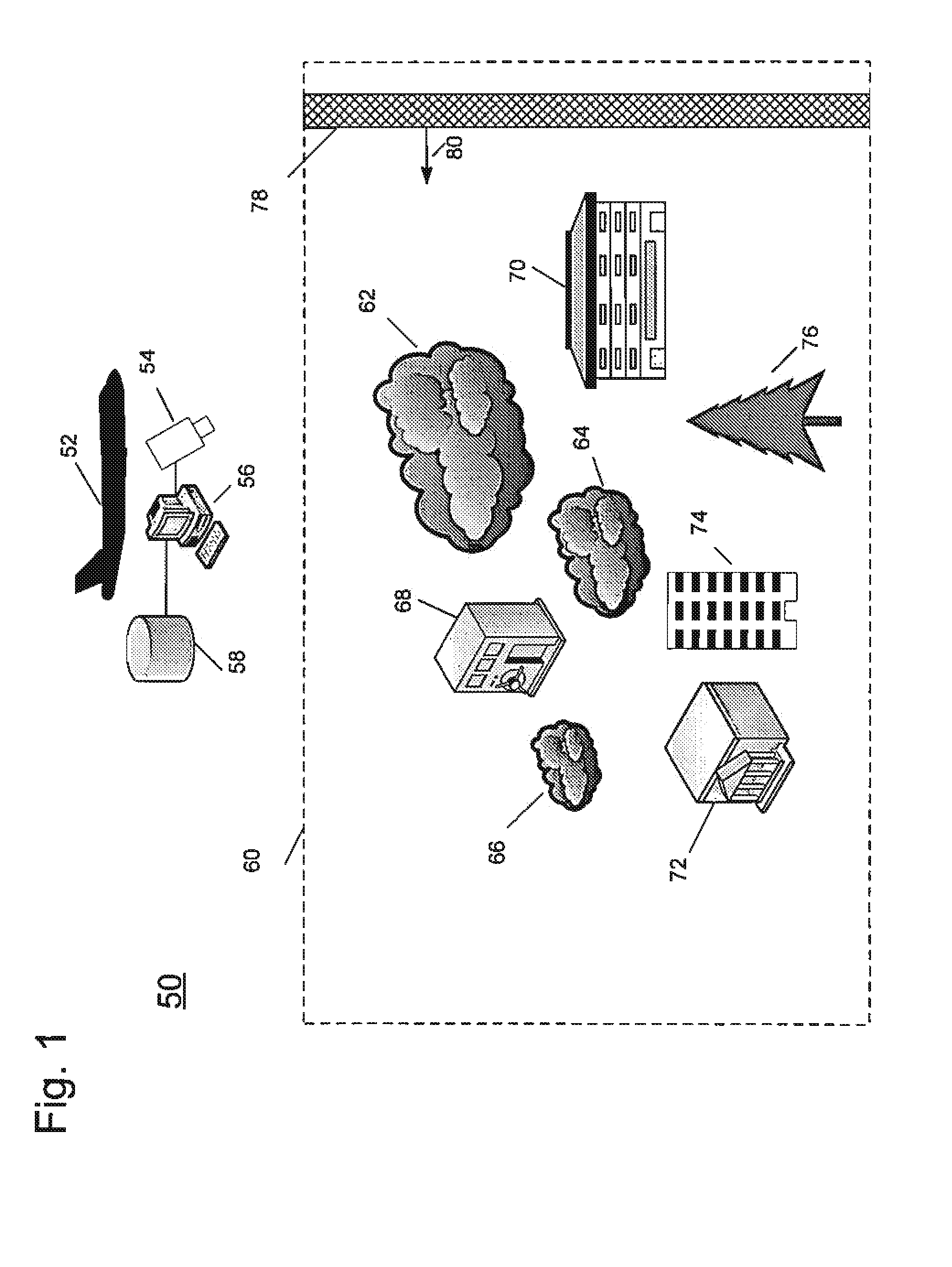
[0018]Various embodiments of the invention are described hereinafter with reference to the figures. Elements of like structures or function are represented with like reference numerals throughout the figures. The figures are only intended to facilitate the description of the invention or as a guide on the scope of the invention. In addition, an aspect described in conjunction with a particular embodiment of the invention is not necessarily limited to that embodiment and can be practiced in conjunction with any other embodiments of the invention.

[0019]The prior art systems described above do not work well in detecting many gases. Gases frequently have low spectral radiance energy emissions and may be hidden in noisy environments including other elements emitting energy at similar wavelengths. In addition, the backgrounds upon which the gases are imposed change spectral radiance due to temperature changes, changes in the atmosphere, solar and thermal changes, time of day etc. and the...


PUM


Abstract

A system and method for detecting, tracking and identifying a gas plume. The system comprises a processor and a detector in communication with the processor. The detector is effective to detect spectral radiance from a region of interest to detect first and second detected spectral radiance data with a known time difference. A database is in communication with the processor, the database includes a library. The processor is effective to create at least a first image and a second image from the first and second detected spectral radiance data and co-register the first and second images to produce a first co-registered image and a second co-registered image. The processor is further effective to subtract the first co-registered image from the second co-registered image to produce a difference image and generate a cluster region around a difference region in the difference image. The processor is further effective to analyze the spectral radiance from the cluster region to produce a spectral characteristic curve; and correlate the spectral characteristic curve against the library to identify the gas plume.

Description

PRIORITY CLAIM[0001]This application claims priority to U.S. Provisional Patent Application No. 61 / 100,476 filed Sep. 26, 2008, entitled “Temporal Hyperspectral Change Detection Method for Gas Plume Detection, Tracking and Identification” the entirety of which is hereby incorporated by reference.BACKGROUND OF THE INVENTION[0002]1. Field of the Invention[0003]This disclosure relates to image processing and, more particularly, to a system and method for identifying a gas plume in a region of interest.[0004]2. Description of the Related Art[0005]Lethal gas plumes often exhibit very low concentration levels of gaseous effluents. If such gases are released in an environment, it is sometimes quite difficult to detect their presence. For example, some highly toxic gases such as Sarin or VX are not visible to the human eye and have low levels of emissions compared with surrounding environments. Prior art techniques exist for creating a digital image of energy emissions from a region of inte...

Claims


Application Information

Patent Timeline
IPC IPC(8): G01N21/84
CPCG01N21/3504G01N21/3581G01N2021/1795G06T2207/10036G06T7/0002G06T7/2053G01N2021/3531G06T7/254
Inventor GORIN, BRIAN A.
Owner BAE SYST INFORMATION & ELECTRONICS SYST INTERGRATION INC
Why Eureka
Try Eureka