
Method and apparatus for improving safety during exposure to a monochromatic light source

a monochromatic light source and safety technology, applied in the field of laser-based light sources, can solve the problems of increasing the potential for eye damage, burning a small portion of the eye retina, and general consideration of laser systems as high-risk systems, and achieve the effect of improving the bodily safety of bystanders

Inactive Publication Date: 2005-10-20
CANDELA CORP
View PDF71 Cites 101 Cited by
  • Summary
  • Abstract
  • Description
  • Claims
  • Application Information

AI Technical Summary

Benefits of technology

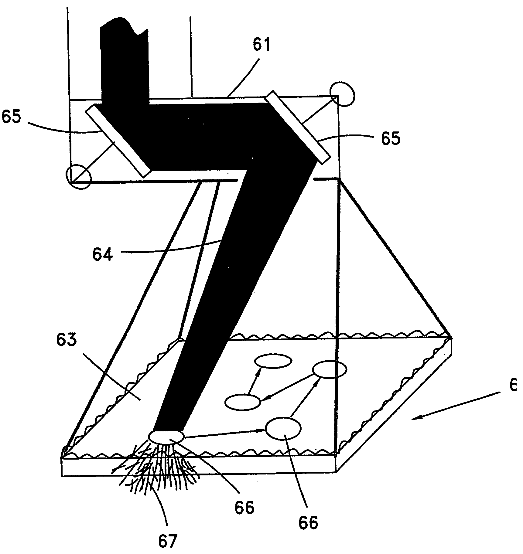
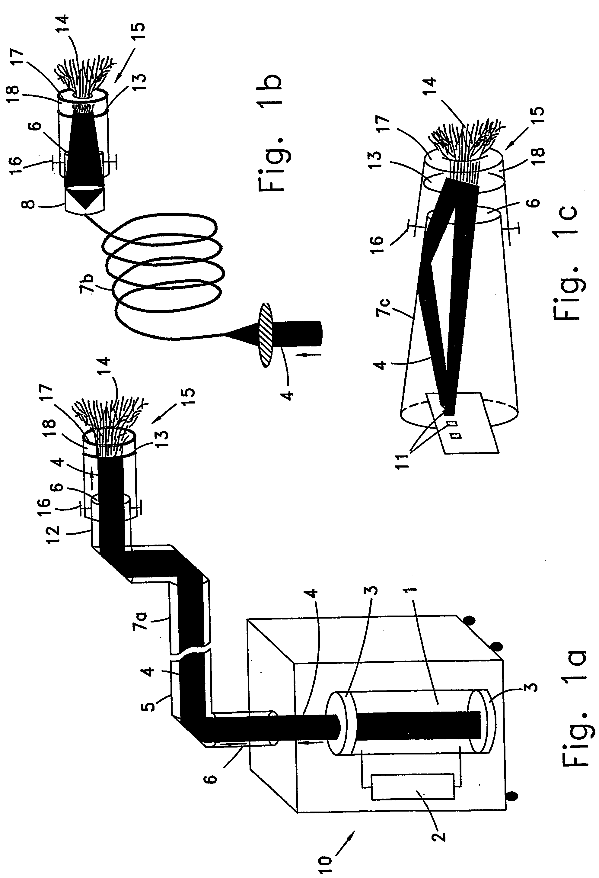
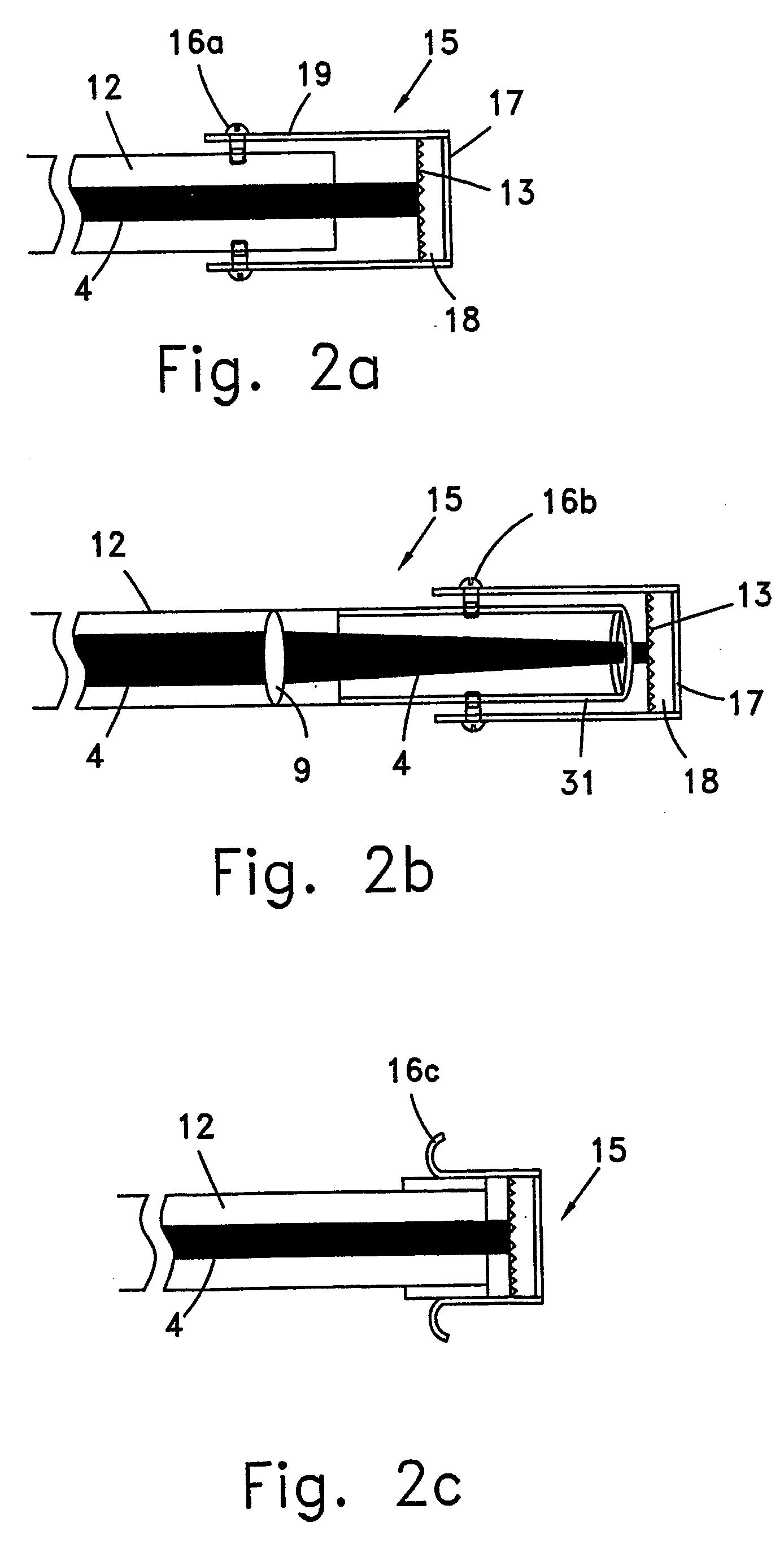
[0022] The present invention comprises a method of improving bodily safety of bystanders exposed to a monochromatic light source, comprising: providing a monochromatic light source with a distal end, causing said monochromatic light to diverge at said distal end, whereby at a first position of said distal end relative to a target the energy density of an exit beam from said distal end is substantially equal to the energy density of the monochromatic light and at a second position of the distal end relative to a target the energy density of the light emitted from said distal end is significantly less than the energy density of the monochromatic light.

Problems solved by technology

Current medical and aesthetic laser systems are generally considered as high-risk systems due to the fact that the light beam that is emitted from these systems has only a low divergence, or even convergence.
In the case of a laser source emitting visible, or near visible, light, damage could result by burning a small portion of an eye retina, if the beam is accidentally aimed at the eyes of a bystander.
Such beam could even cause blindness.
Potential eye damage is further increased when using near infrared lasers which emit invisible radiation, since bystanders are unaware that a laser beam is being fired.
Also, the extremely short pulse duration of a beam emitted by many laser systems does not allow enough time for one to react, such as by blinking or moving the eyes, as a result of the accidental firing of a laser beam.
For example, such precautions might include the use of expensive (and inconvenient to use) coated protective eyeglass filters with very high optical density and damage-resistant values to optical radiation (i.e. thermal and mechanical durability).
Of all the risks, the risk of permanently blinding people is the most common and severe.
High-class Continuous Working (CW) lasers, such as Nd:YAG, KTP and Diode lasers (at any wavelength between 630 and 1320 nm) are also known for their risk in causing blindness.
Moreover, these lasers are at times used for cosmetic surgery in the vicinity of the eyes, such as for eyebrow removal or skin rejuvenation around the eyes, and therefore such surgery causes additional risk to eye damage.
There is also a risk of hair and skin burns, if the laser units are mishandled, even if operated in remote locations.
Should a collimated laser beam hit a flammable material in the treatment room, a fire may result.
The risks associated with coherent lasers do not stem only from the capability to generate highly collimated beams, but also from the capability to concentrate the entire laser energy onto a confined surface from a distance, with the appropriate focusing optics.
Conventional non-coherent light sources, although safe to use, cannot be imaged without substantial intensity loss.
All of the above-mentioned risks associated with visible and near infrared lasers have led to very strict governmental regulations regarding the operation of medical and aesthetic laser-based systems, causing a substantial increase in the expenses of both manufacturers and operators of these systems.
According to some of these governmental regulations, the operation of laser devices / systems is restricted to trained and skilled personnel, i.e. technicians or nurses under the supervision of a physician.
In many countries, non-medical personnel such as cosmeticians are not allowed to handle laser-based systems at all.
There exists, therefore, a risk of directing a laser beam having an incorrect wavelength to a selected treated organ / tissue, which may severely damage this organ / tissue.
Even if the organ is treated by a laser beam having the correct wavelength, there is always a risk that the laser beam might be mistakenly aimed to other areas, which are highly sensitive to the selected wavelength, thereby resulting in damage.
However, IPL systems have reduced spectral selectivity due to their broad spectral bands.
Consequently, IPL-based systems offer rather limited treatment capabilities in comparison to laser-based systems.
The systems disclosed herein are also extremely risky to the eyes since the laser energy density is essentially preserved within a relatively small solid angle to which an eye may be exposed, even after having transporting the beam to a distal confined spot.
The generation of a laser beam having a large divergent solid angle is disadvantageous, according to prior art methods, particularly since efficient imaging and focusing on the skin or into the skin would be precluded.
Also, the laser energy density associated with these two patents is efficacious only when the diffusing, focusing plate is at a distance from a target, and is not efficacious when located adjacent to a target.
However, as already described, there is a trade-off between the efficiency of a laser device and the potential risk in its operation; i.e., as the beam is more focused, the treatment becomes more risky.
The prior art laser units are not capable of generating a beam with a high energy level that may be used for aesthetic or surgical procedures without presenting a risk of injury to bystanders or damage to property, such as by igniting a fire.

Method used


Image

  • Method and apparatus for improving safety during exposure to a monochromatic light source
  • Method and apparatus for improving safety during exposure to a monochromatic light source
  • Method and apparatus for improving safety during exposure to a monochromatic light source

Examples


example 1

[0198] An experiment was performed to demonstrate the operating principles of the present invention in which transparent light diffusing adhesive “Magic Tape,” manufactured by 3M, having a thickness of 100 microns was attached to the distal end of an Alexandrite laser unit having a diameter of 8 mm. The energy level of the laser beam is 11 J / pulse. The laser beam was directed to the white (rear) side of a black developed photographic paper having a thickness of 300 microns. For comparison, the laser beam was also directed to the photographic paper without the use of the adhesive tape.

[0199] The ablation of the black paper after the beam had propagated and scattered through the white paper provides a visual simulation of the capability of the laser beam to penetrate transparent light-scattering skin in order to treat black hair follicles (or any other type of lesion) under the skin.

[0200] The energy of the laser beam transmitted through the adhesive tape, which caused the laser bea...

example 2

[0203] In a second experiment a long pulse Alexandrite laser unit having a wavelength of 755 nm, pulse duration of 40 msec, and having an energy density of 25 J / cm2 was used for hair removal. A diffusing unit with an ultra-densely woven polymer-based diffuser having a half angle of 15 degree produced by Barkan or a holographic diffuser produced by Physical Optics Corporation (USA) having a half angle of 40 degrees was employed. The diffusers were used in a one-time basis. Chilling gel was applied between the diffuser and the skin.

[0204] Each pulse of a laser beam scattered by a diffusing unit formed a spot of 5.5 mm on various skin locations including arms, bikini lines and armpits of 10 patients. Full hair removal was noticeable immediately after the firing of the laser beam. Each spot was compared to a control area with an identical diameter formed by an unscattered laser beam generated by the same laser unit with similar parameters, and similar results were achieved. Hair did no...

example 3

[0205] A long pulse Alexandrite laser unit having a wavelength of 755 nm, pulse duration of 40 msec, and having an energy level of 1-20 J is suitable for hair removal.

[0206] The diameter of the diffusing unit is 7 mm, and its scattering half angle is 60 degrees. A diffusing. unit comprising a diffuser with a small scattering angle, a highly divergent lens and a light guide is added to the distal end of the laser unit.

[0207] The prior art energy density of 10-50 J / cm2 is not significantly reduced with the employment of a diffusing unit. The laser unit operates at 25 J / cm2 and generates a radiance of 8 J / cm2 / sr. Since the acceptable radiance limit according to ANSI Z 136.1 is 4.3 J / cm2 / sr, bystanders are required to use protective eyeglasses with 50% optical attenuation, an attenuation similar to that of sunglasses and an order of 100,000 less than typical protective eyeglasses worn during operation of a laser unit. For a larger target area, a scanner such as the Epitouch model manu...


PUM


Abstract

A method and apparatus are disclosed for improving bodily safety during exposure to a monochromatic light source by diverging the monochromatic light, such as with a highly durable diffuser. At a first position of the distal end of the monochromatic light source the energy density of an exit beam from said distal end is substantially equal to the energy density of the monochromatic light required for desired applications and at a second position of the distal end the energy density of the light emitted therefrom is significantly less than the energy density of the monochromatic light. Accordingly, a laser unit suitable for aesthetic treatment, medical treatment or industrial treatment is converted into an eye safe laser unit. Eye safety is further enhanced by measuring the radiance of the divergent monochromatic light and issuing a warning as a result of a mishap if the radiance of the divergent monochromatic light is greater than a predetermined safe value, and if desired, generating a visible flash prior to the emission of a pulse of monochromatic light to induce an eye of a bystander to blink or to change its field of view in order to avoid staring at the monochromatic light.

Description

FIELD OF THE INVENTION [0001] The present invention is related to the field of laser-based light sources. More particularly, the present invention is related to providing an eye-safe laser beam that is suitable for correcting aesthetic and medical skin disorders that require a very high energy density. Even more specifically, the present invention is related to a method and apparatus for improving bodily safety during exposure to a monochromatic light source by diverging the monochromatic light, such as with a highly durable diffuser, which provides the required energy density of light for desired applications at a very short distance but is inherently safe to the eyes of bystanders. BACKGROUND OF THE INVENTION [0002] Current medical and aesthetic laser systems are generally considered as high-risk systems due to the fact that the light beam that is emitted from these systems has only a low divergence, or even convergence. In these systems a light beam with a high energy density and...

Claims


Application Information

Patent Timeline
Patent Type & Authority Applications(United States)
IPC IPC(8): A45D26/00A61B17/00A61B18/00A61B18/18A61B18/20A61B18/22A61B19/00A61C3/02A61N5/06
CPCA61B18/203A61B19/40A61B2017/00172A61B2018/00023A61B2018/00452A61N5/0616A61B2018/00476A61B2018/1807A61B2018/2261A61B2019/409A61B2018/00458A61B90/04A61B2090/049
Inventor SLATKINE, MICHAEL
Owner CANDELA CORP
Learn More