Information processing apparatus and information processing method

Inactive Publication Date: 2010-04-01
CANON KK
View PDF6 Cites 15 Cited by
  • Summary
  • Abstract
  • Description
  • Claims
  • Application Information

AI Technical Summary

Benefits of technology

[0016]According to the first aspect of the present invention, an information processing apparatus comprising: a plurality of sensor units which are attached to the information processing apparatus in a predetermined arrangement pattern to detect direct/indirect contact; a plurality of presentation units which are attached to the information processing apparatus in a predetermined arrangement pattern to present a tactile stimulus; a first specifying unit which specifies, out of said plurality of sensor units, a sensor unit that has detected direct/indirect contact; a second specifying unit which specifies, based on an arrangement distribution of the sensor unit specified by said first specifying unit and a type of information to be presented via a tactile stimulus, a presentation unit to be driven out of said plurality of presentation units; and a control unit which drives and controls the presentation unit specified by said second specifying unit.
[0017]According to the second aspect of the present invention, an information processing apparatus comprising: a plurality of sensor units which are attached to the information processing apparatus in a predetermined arrangement pattern to detect direct/indirect contact; a plurality of presentation units which are attached to the information processing apparatus in a predetermined arrangement pattern to present a tactile stimulus; a first specifying unit which specifies, out of said plurality of sensor units, a sensor unit that has detected direct/indirect contact; a second specifying unit which specifies, out of said plurality of presentation units, a presentation unit corresponding to the sensor unit specified by said first specifying unit; and a control unit which drives and controls the presentation unit specified by said second specifying unit to generate a preset stimulus pattern to express information to be presented to a user.
[0018]According to the third aspect of the present inv

Problems solved by technology

However, since the physical size of the information transfer area is small, information input or interpretation of output information is more difficult than before the downsizing or conversion into information terminals.
When visually outputting information, as the information presentation area becomes smaller, the visually output infor

Method used


Image

  • Information processing apparatus and information processing method
  • Information processing apparatus and information processing method
  • Information processing apparatus and information processing method

Examples


first embodiment

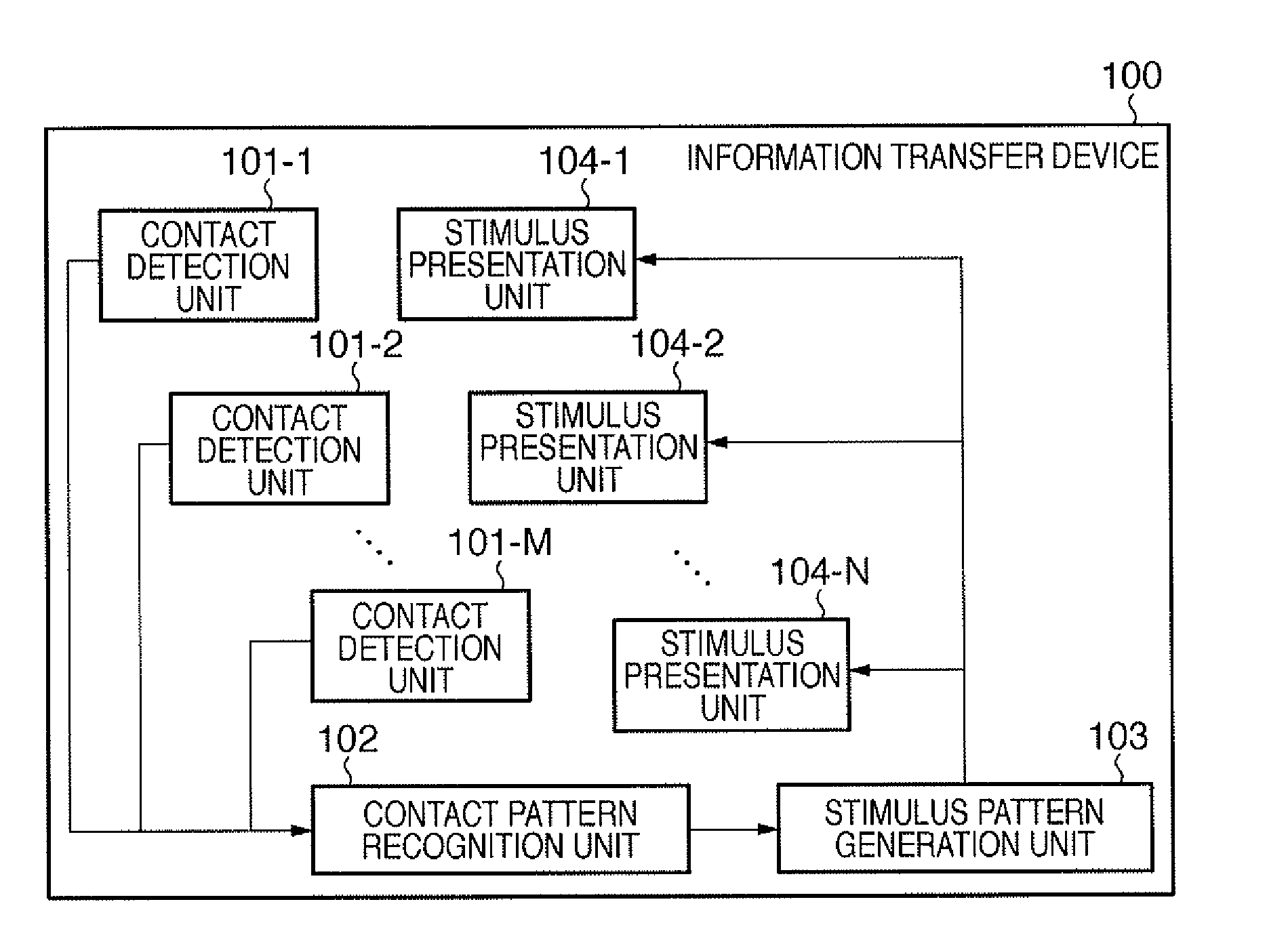
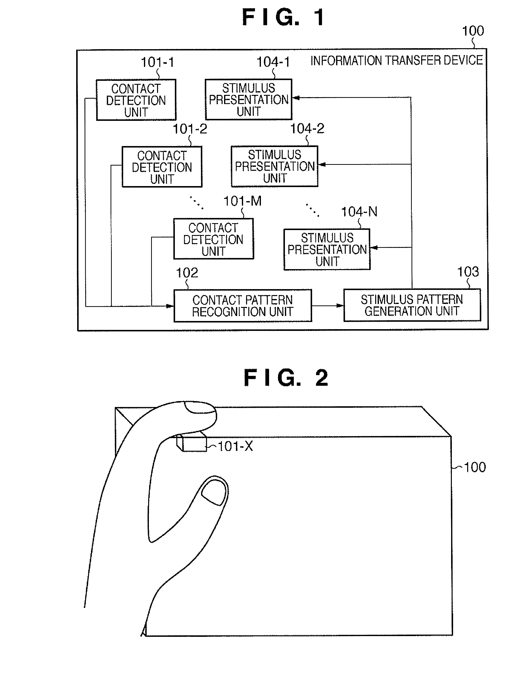
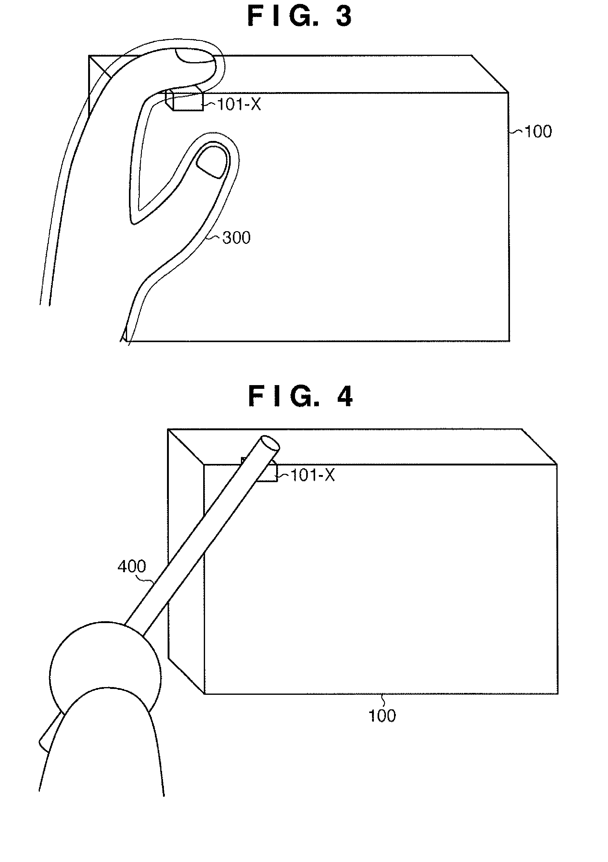
[0050]An information processing apparatus according to this embodiment is an information transfer device which is gripped and operated by a user, and has a function of presenting information to the user based on a tactile stimulus. This information transfer device is, for example, a digital camera or an ultrasonic probe a user can hold in hands and operate. Using a tactile stimulus, the device notifies the user of, e.g., operation navigation information representing how to move the information transfer device, a processing result output from the information transfer device in response to a user input, and information of some kind the information transfer device has externally acquired by measurement or communication.

[0051]The information transfer device will be described below in more detail.

[0052]

[0053]FIG. 1 is a block diagram showing an example of the functional arrangement of an information transfer device according to this embodiment. As shown in FIG. 1, an information transfer...

second embodiment

[0081]1000>

[0082]FIG. 10 is a block diagram showing an example of the functional arrangement of the information transfer device 1000. As shown in FIG. 10, the information transfer device 1000 includes contact detection units 1001 and 1002, stimulus presentation units 1003 and 1004, and a stimulus device driving unit 1005.

[0083]The contact detection units 1001 and 1002 perform the same operation as that of the contact detection units 101-1 to 101-M and are arranged on or inside the information transfer device 1000 in a predetermined arrangement pattern. Each of the contact detection units 1001 and 1002 (first and second contact detection units) outputs a signal representing a detection result to the stimulus device driving unit 1005.

[0084]The stimulus presentation unit 1003 is the same as each of the stimulus presentation units 104-1 to 104-N described in the first embodiment. The stimulus presentation unit 1003 is arranged on or inside the information transfer device 1000 and, more ...

third embodiment

[0108]An information transfer device according to this embodiment transfers information to a user via a tactile stimulus, as in the second embodiment. In the information transfer device of this embodiment, each of the stimulus presentation units 1003 and 1004 described in the second embodiment further includes a plurality of stimulus presentation units (sub-stimulus presentation units). That is, including a plurality of stimulus presentation units into, e.g., the stimulus presentation unit 1003 enables finer (more correct) information presentation.

[0109]1700>

[0110]FIG. 17 is a block diagram showing an example of the functional arrangement of the information transfer device 1700 according to this embodiment. As shown in FIG. 17, the information transfer device 1700 includes contact detection units 1701 and 1702, stimulus presentation units 1703-1 to 1703-N, and a stimulus device driving unit 1705.

[0111]The contact detection units 1701 and 1702 are the same as the contact detection un...


PUM


Abstract

Contact detection units (101-1-101-M) are attached to an information transfer device (100) in a predetermined arrangement pattern to detect direct/indirect contact. Stimulus presentation units (104-1-104-N) are attached to the information transfer device (100) in a predetermined arrangement pattern to present a tactile stimulus. A contact pattern recognition unit (102) specifies a contact detection unit that has detected direct/indirect contact. A stimulus pattern generation unit (103) specifies, based on the arrangement distribution of the specified contact detection unit and the type of information to be presented via a tactile stimulus, a stimulus presentation unit to be driven, and drives and controls the specified stimulus presentation unit.

Description

BACKGROUND OF THE INVENTION[0001]1. Field of the Invention[0002]The present invention relates to a technique of presenting a tactile stimulus to a user to notify him / her of information.[0003]2. Description of the Related Art[0004]CPUs having improved throughput and miniaturization of various kinds of devices are accelerating downsizing of general-purpose information terminals represented by a PC and sophistication of mobile information terminals represented by a cellular phone. Even a small single-function device such as a barcode reader behaves as a simple information terminal capable of information operation to some degree by having a high-level information processing function or communication function.[0005]Downsizing information terminals or converting small single-function devices into information terminals enables to widen their use range. However, since the physical size of the information transfer area is small, information input or interpretation of output information is mo...

Claims


Application Information

Patent Timeline
IPC IPC(8): H04B3/36
CPCG06F3/016H04B3/36G09B21/003G06F3/03547
Inventor ANABUKI, MAHORONOGAMI, ATSUSHISONODA, TETSURI
Owner CANON KK
Why Eureka
Try Eureka