Multi-Section Visual Display having Overlapping Structure

a visual display and multi-section technology, applied in the field of multi-section visual displays, can solve the problems of increasing the thickness of the apparatus, wasting additional space, and discontinuous sections, and achieve the effect of reducing the spacing required and reducing the no-light border area

Active Publication Date: 2010-04-01
AU OPTRONICS CORP
View PDF4 Cites 16 Cited by
  • Summary
  • Abstract
  • Description
  • Claims
  • Application Information

AI Technical Summary

Benefits of technology

[0008]Hence, an aspect of the present invention is to provide a multi-section visual display having an overlapping structure for reducing the no-light borde...

Problems solved by technology

However, since the frame border area located at four edges of a LCD cannot display any image, there is an invalid display area (i.e. a border area with no light emitted and is called no-light border area hereinafter) existing in an intersection area between two screens of a multi-section LCD, thus resulting a discontinuous section appearing in an image crossing the two screens.
However, as to commercial liquid crystal displays, their border areas are all more than 1 mm in width, and in the design of a conventional edge-to-edge foldable multi-section display, its total border area is the summation of each screen's border area, and thus the conventional edge-to-edge fo...

Method used


Image

  • Multi-Section Visual Display having Overlapping Structure
  • Multi-Section Visual Display having Overlapping Structure
  • Multi-Section Visual Display having Overlapping Structure

Examples


case 1

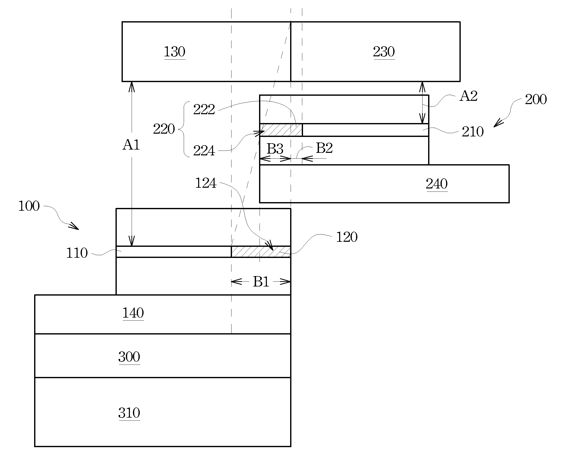
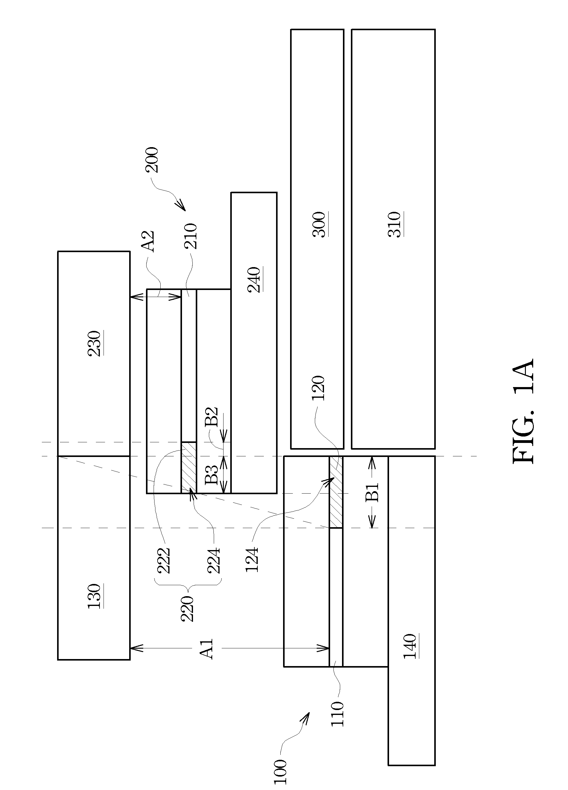
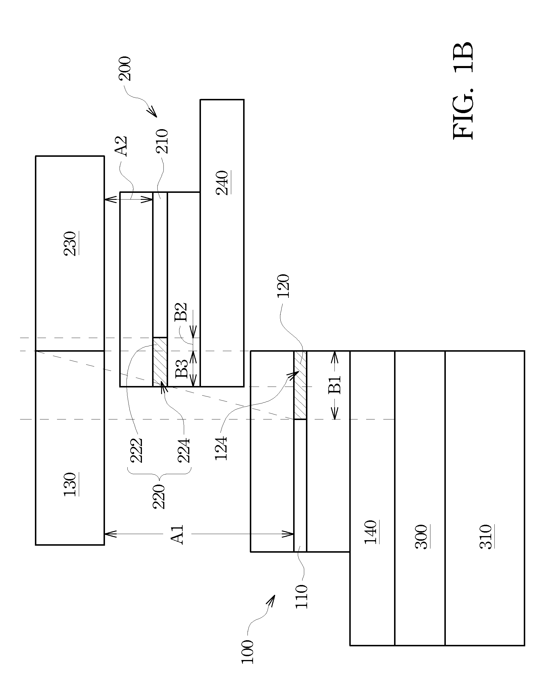
[0032] When an outer boundary of the first border area 120 is aligned with an intersection of the first magnifying lens 130 and the second magnifying lens 230, the first spacing A1, the second spacing A2, the width B1 of the first border area 120, the width B2 of the non-overlap portion 222, the width B3 of the overlap portion 224, the focal length F and the half width W of lens satisfying the following relationship:

WF=B1A1=B2A2=B3A2(2)

case 2

[0033] When the outer boundary of the first border area is not aligned with the intersection of the first magnifying lens and the second magnifying lens, the first spacing A1, the second spacing A2, the width B2 of the non-overlap portion 222, the focal length F and the half width (W) of lens satisfying the following relationship:

A1=(B2W)×F+T(3)

[0034]wherein T=A1−A2; i.e. the distance between the first display panel 110 and the second display panel 210.

Design Principle 2

[0035]Referring to FIG. 5B, FIG. 5B is a schematic diagram for explaining another design principle of the present invention, wherein the first magnifying lens has a first focal length F1 and a first half width W1 of lens, and the second magnifying lens has a second focal length F2 and a second half width W2 of lens, the first spacing A1, the second spacing A2, the width B1 of the first border area 120, the width B3 of the overlap portion 224, the first focal length F1, the second focal length F2, the first half width...


PUM


Abstract

A multi-section visual display having an overlapping structure is disclosed, and includes a first magnifying lens, a second magnifying lens, a first display apparatus having a first display panel and a second display apparatus having a second display panel, wherein the second display apparatus is disposed between the first magnifying lens and the first display apparatus, and the second magnifying lens is aligned with the first magnifying lens in an edge-to-edge manner. While at an operation state, a first border area of the first display panel is partially overlapped with a second border area of the second display panel, thereby reducing the non-display area needing shielding by using a virtual image display from the first display panel/magnifying lens to shield a portion of the second border area, thus reducing the space required between the magnifying lenses and the first display panel.

Description

RELATED APPLICATIONS[0001]This application claims priority to Taiwan Application Serial Number 97137582, filed Sep. 30, 2008, which is herein incorporated by reference.BACKGROUND[0002]1. Field of Invention[0003]The present invention relates to a multi-section visual display. More particularly, the present invention relates to a multi-section visual display having an overlapping structure.[0004]2. Description of Related Art[0005]Current designs of various electronic information apparatuses are developed towards the trend of lightness and compactness for convenient portability. For example, mobile phones and personal digital assistants are designed towards the direction of lightness, thinness, shortness and smallness. For preventing the screen size of a portable mobile apparatus from affecting the visual clearness or causing eye tiredness, and further meeting the multi-media requirements of future portable mobile apparatuses, a foldable multi-section liquid crystal display (LCD) is pr...

Claims


Application Information

Patent Timeline
IPC IPC(8): G02F1/1333
CPCG02B27/1066G02B27/126G02F1/13336G02F1/133526H04M2250/16G02F2001/133331G06F1/1616G06F1/1624H04M1/027G02F1/1336G02F1/133331
Inventor HWU, KEH-LONGKAO, KUO-FENGLEE, SEOK-LYUL
Owner AU OPTRONICS CORP
Why Eureka
Try Eureka