Method for Defining an Individual Coordination System for a Breast of a Female Patient

a technology of individual coordination and breast, applied in the field of breast diagnosis, can solve the problem of almost impossible to determine the location of a particular object in the breas

Inactive Publication Date: 2010-04-01
MIR MEDICAL IMAGING RES HLDG
View PDF95 Cites 7 Cited by
  • Summary
  • Abstract
  • Description
  • Claims
  • Application Information

AI Technical Summary

Problems solved by technology

It is almost impossible to determine the location of a particular object within the breast because the o

Method used


Image

  • Method for Defining an Individual Coordination System for a Breast of a Female Patient
  • Method for Defining an Individual Coordination System for a Breast of a Female Patient
  • Method for Defining an Individual Coordination System for a Breast of a Female Patient

Examples


Embodiment Construction

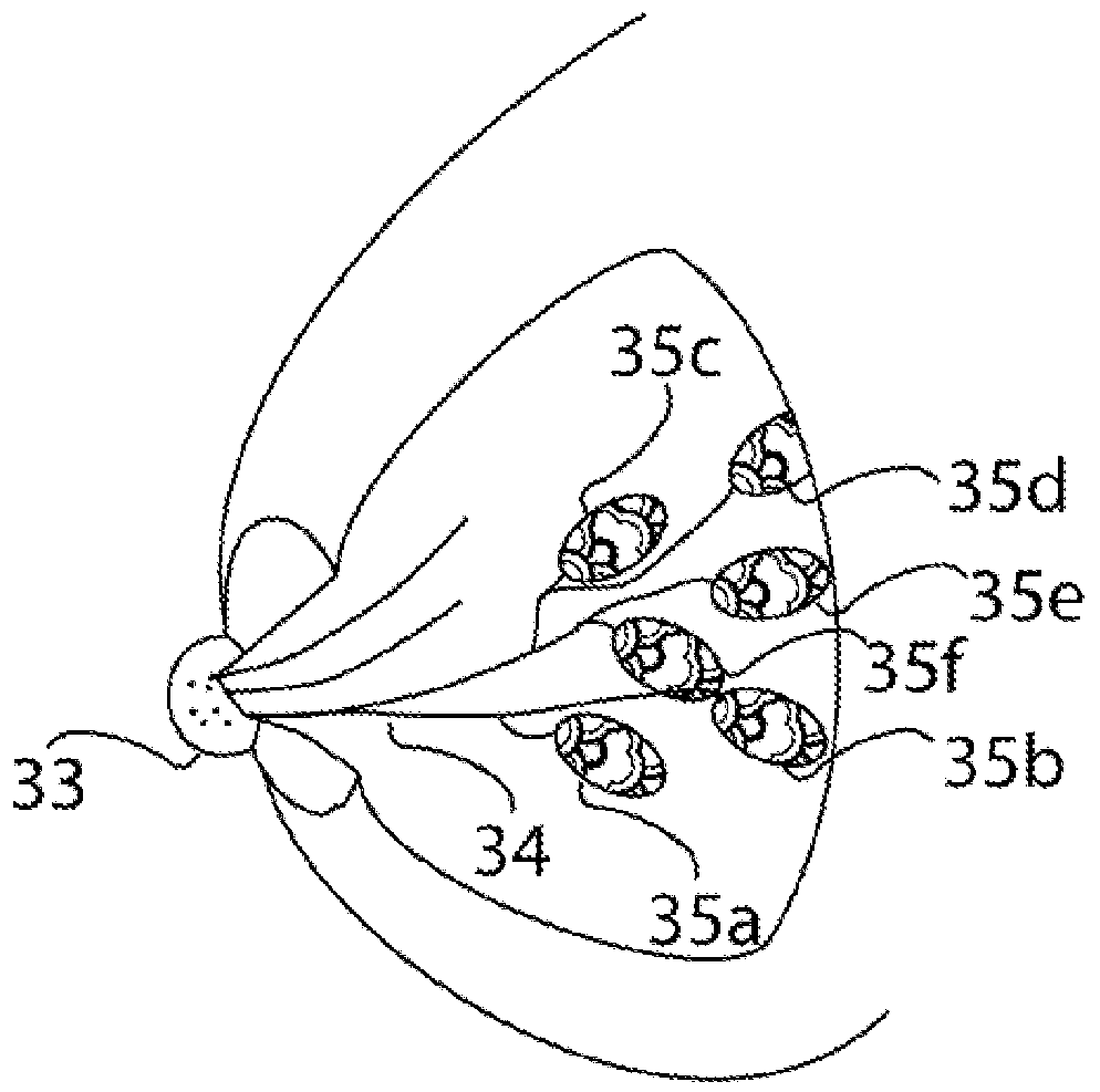
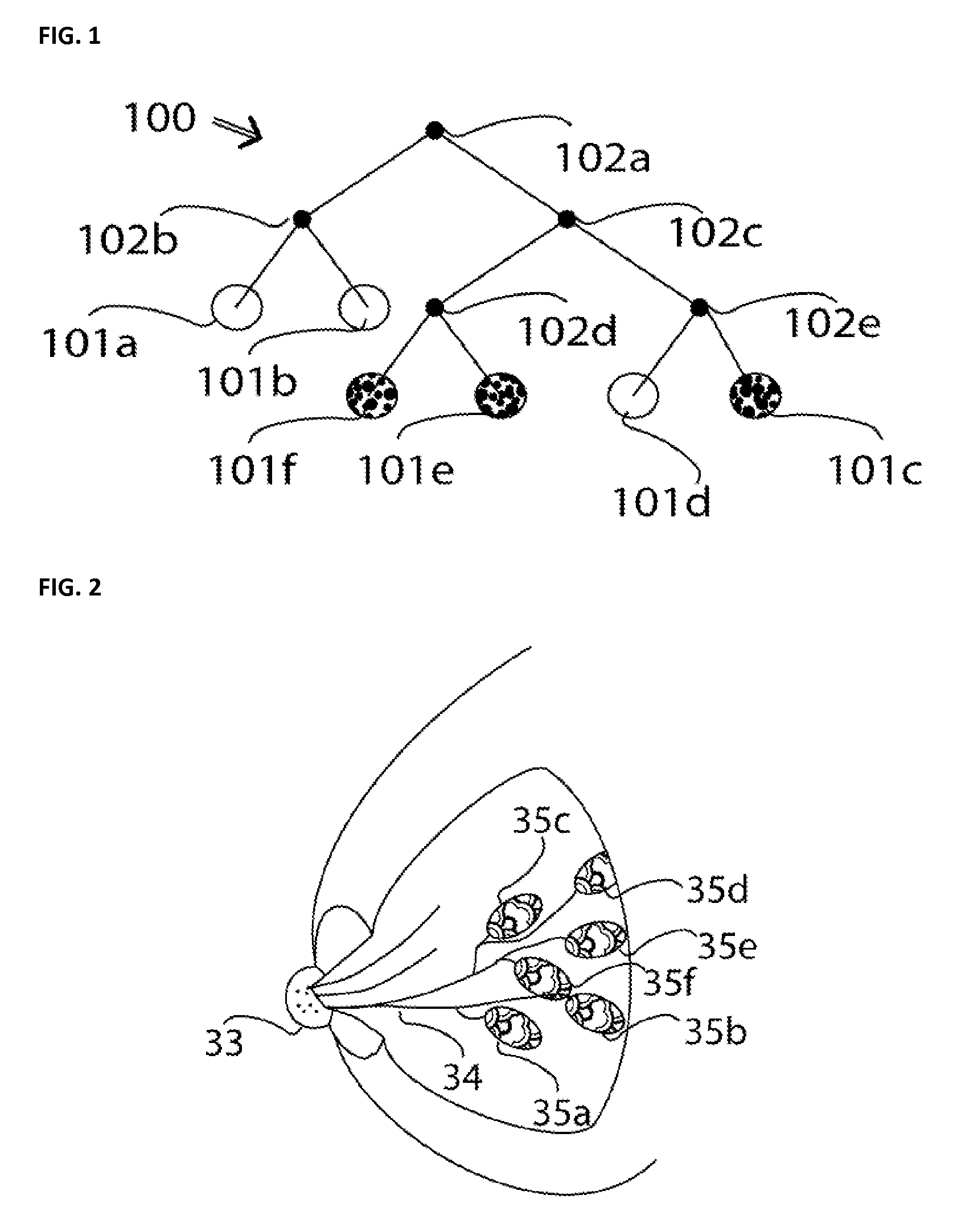
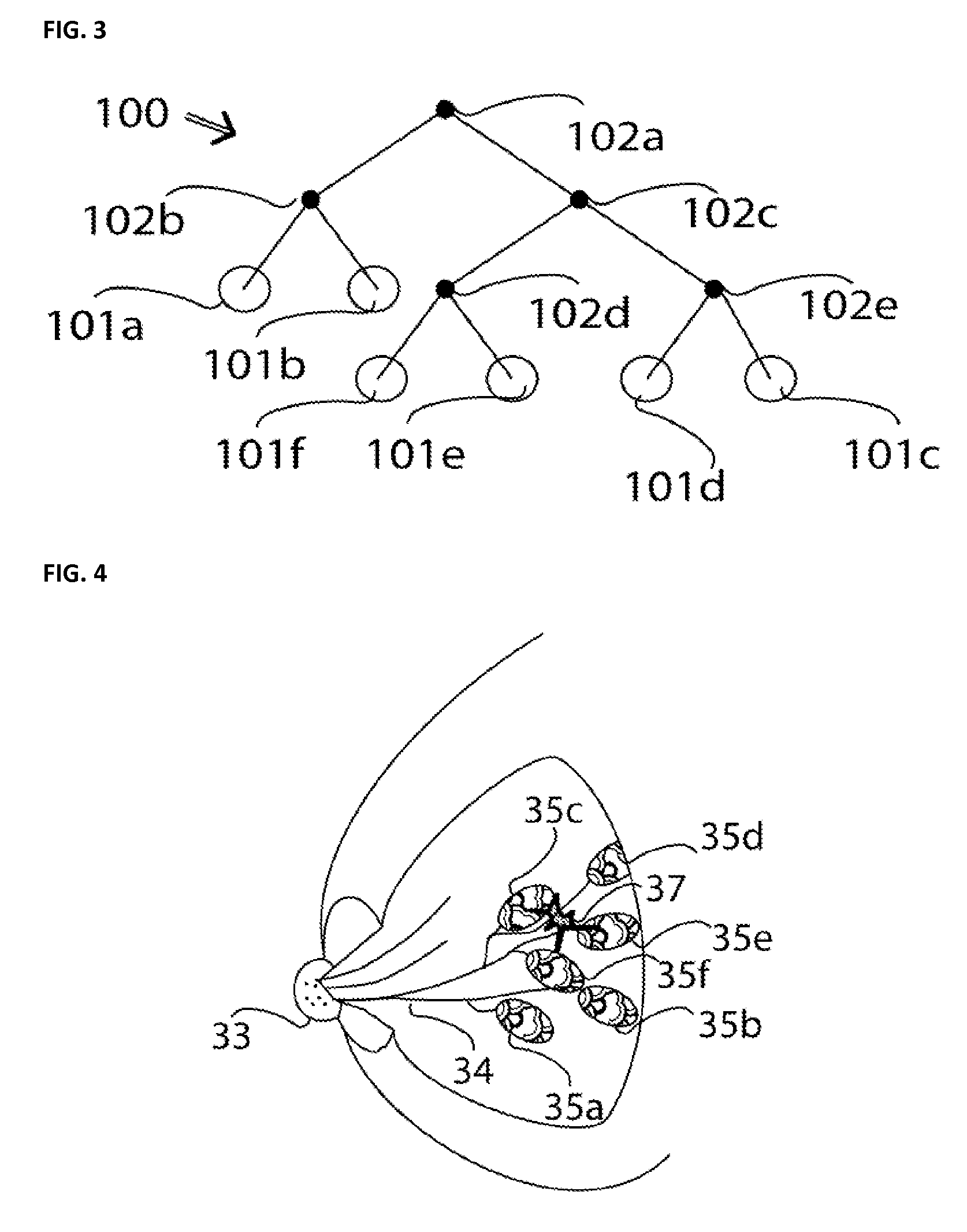
[0018]FIG. 1 shows a tree-type structure 100 as can be produced with the method described herein. FIG. 2 schematically shows an inner structure of a female breast from which this tree-type structure has been produced. The uppermost node 102a of the tree-type structure corresponds to the position of the breast nipple 33. Starting out from this node, there follows in the left branch another node 102b with leaves 101a and 101b. These leaves correspond to glandular bodies 35a and 35b on a mammary or lactiferous duct 34. Starting again from the uppermost node, in the right branch the node 102c is followed on the left by the node 102d with the leaves 101f corresponding to the glandular body 35f and 101e corresponding to the glandular body 35e, and on the right by the node 102e with the leaves 101d corresponding to the glandular body 35d, and 101c corresponding to the glandular body 35c. For an exact localization, additional features such as the size of the mammary glands, e.g. the volume ...


PUM


Abstract

A method is provided for determining a position of an object within a breast of a female patient in a simple manner from a three-dimensional exposure taken of the breast. A simplified model is made of an internal structure of a breast having glandular bodies leading via lactiferous ducts to an outlet at a nipple. A particularly advantageous model is a tree-type structure in which branches correspond to lactiferous ducts and leaves correspond to glandular bodies. Furthermore, a determination is made of whether the object has contact with an element of the tree-type structure. Alternatively, a distance to an element of the tree-type structure is established. By correlating tree-type structures derived from various exposures taken on the same breast, the location of the object can be unequivocally established.

Description

PRIORITY CLAIM[0001]This application claims priority to pending German Application No. DE 102008042430.7 filed on Sep. 29, 2008.BACKGROUND OF THE INVENTION[0002]1. Field of the Invention[0003]The invention relates to a diagnostic method for application to a female breast. It makes possible a determination of a position of an object within the breast by evaluation of three-dimensional exposures of the breast, as produced for example by a CT scanner.[0004]2. Description of Related Art[0005]Various instruments such as X-ray machines or also computed tomography (CT) scanners are known for examining a female breast. A CT scanner of this kind is described, for example, in U.S. Patent Application Publication No. 2007 / 0094950. An X-ray facility with a rotating gantry which has an X-ray tube and a detector is located below a patient table on which a patient to be examined rests. A breast of the patient to be examined projects through an opening in the patient table and into a ray path of the...

Claims


Application Information

Patent Timeline
IPC IPC(8): A61B6/04G06K9/00
CPCA61B5/015A61B6/027A61B5/704A61B6/032A61B6/035A61B6/0435A61B6/06A61B6/107A61B6/502A61B6/583A61B18/00A61B2017/00084A61B2019/205A61B2019/5238A61B2019/524G01K11/30G06T7/0012G06T7/0083G06T2207/10081G06T2207/30068G06T2207/30096A61B5/4312A61B6/4275A61B90/17A61B2090/376A61B2090/3762G06T7/74G06T7/12
Inventor KALENDER, WILLISCHILLING, HARRY
Owner MIR MEDICAL IMAGING RES HLDG
Why Eureka
Try Eureka