Lens frame, lens assembly and image-taking apparatus

a technology which is applied in the direction of television system, printing, instruments, etc., can solve the problems of complex structure of lens frame and assembly work, inability to achieve predetermined performance, and sequential movement of spacing rings and lenses inside the lens assembly

Active Publication Date: 2010-04-01
NANCHANG O FILM OPTICAL ELECTRONICS TECH CO LTD
View PDF21 Cites 4 Cited by
  • Summary
  • Abstract
  • Description
  • Claims
  • Application Information

AI Technical Summary

Benefits of technology

[0039]According to the image-taking apparatus of the present invention, when this image-taking apparatus is installed in an automobile, the lens in the lens frame is prevented from shifting even when there occurs movement such as vibration produced while running or shock caused by acceleration or deceleration. Accordingly, predetermined optical performance is maintained.

Problems solved by technology

Therefore, after the lens assembly 1 illustrated in FIG. 1 is installed in an automobile, there is a possibility that the spacing rings and the lenses disposed inside the lens assembly may sequentially move in response to movement such as vibration produced while running or shock caused by acceleration or deceleration.
If the spacing rings and the lenses sequentially move, predetermined performance cannot be achieved.
However, this makes the structure of the lens frame as well as the assembly work complicated, which is a problem.

Method used


Image

  • Lens frame, lens assembly and image-taking apparatus
  • Lens frame, lens assembly and image-taking apparatus
  • Lens frame, lens assembly and image-taking apparatus

Examples


Embodiment Construction

[0044]An embodiment of the present invention will be described.

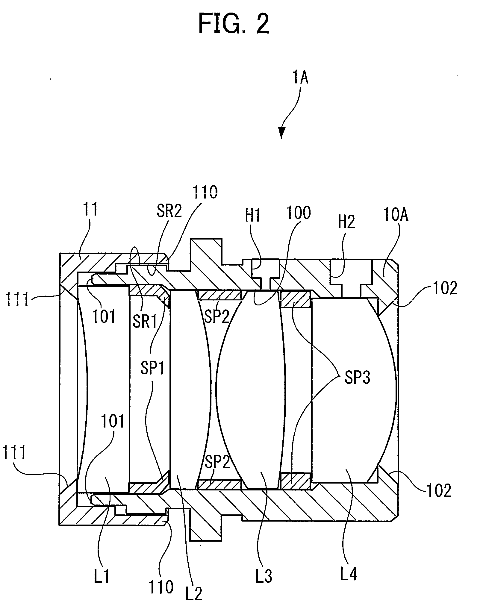
[0045]FIG. 3 is a diagram that depicts a lens assembly 1B that is an embodiment of the present invention.

[0046]FIG. 3 illustrates the structure of the lens assembly 1B having a lens frame 10B in which concave sections K1 and K2, instead of the holes H1 and H2 illustrated in FIG. 2, are formed at positions corresponding to lenses L3 and L4 of the lens frame 10B, respectively.

[0047]The concave sections K1 and K2 formed in the lens frame 10B illustrated in FIG. 3 are externally open, and a spacing wall is formed between a hollow part 100 and each of the concave sections K1 and K2. Into the concave sections K1 and K2, an adhesive for fixing the lenses L3 and L4 that are optical members inserted into the lens frame 10B is injected.

[0048]When injected into the concave sections K1 and K2 illustrated in FIG. 3, the adhesive passes through multiple pores of the lens frame 10B made of porous ceramic and reaches the inner wall of t...


PUM


Abstract

A lens assembly made of porous ceramic is provided with concave sections into which an adhesive for fixing lenses inserted into a lens frame is injected. Each of the concave sections has an outward opening and a spacing wall provided between a hollow part of the lens frame and the opening. The adhesive injected into the concave sections passes through multiple pores in the lens frame made of porous ceramic, and reaches the periphery of each of the lenses, thereby fixing the lenses to an inner wall of the hollow part of the lens frame.

Description

BACKGROUND OF THE INVENTION[0001]1. Field of the Invention[0002]The present invention relates to a lens frame into which two or more lenses are inserted, a lens assembly equipped with the lens frame, and an image-taking apparatus provided with the lens assembly.[0003]2. Description of the Related Art[0004]In recent years, automobiles have been provided with cameras. Meanwhile, nowadays, automobiles are equipped with display screens thanks to the widespread use of car navigation systems. Therefore, many of cameras installed in automobiles can display the state of a blind spot for a driver on a display screen provided in front of the driver's seat.[0005]Incidentally, automobiles may be left outdoors in hot summer and in freezing winter and therefore, a camera installed in an automobile is required to operate properly over an extremely wide range of temperatures. In order to guarantee the proper operation of a vehicle-mounted camera, a lens assembly employed in such a camera needs to b...

Claims


Application Information

Patent Timeline
Patent Type & Authority Applications(United States)
IPC IPC(8): G03B17/00G02B7/02
CPCG02B7/025G03B21/22G03B1/56G02B2207/107
Inventor TAKI, IKUOSASAKI, RYOTASAKAI, YUYATANAKA, YASUNORI
Owner NANCHANG O FILM OPTICAL ELECTRONICS TECH CO LTD
Why Eureka
Try Eureka