Electric Connection Clamp or Terminal Clamp

a technology of electric connection and clamping rod, which is applied in the direction of coupling contact members, contact members penetrating/cutting insulation/cable strands, electrical apparatus, etc., can solve the problems of unintentional tilting of the clamp spring, inability to detach the clamp spring from the metal part, and increased pressure force. , to achieve the effect of simple and exact connection of an electrical conductor, destruction of the clamp spring

Active Publication Date: 2010-04-01
PHOENIX CONTACT GMBH & CO KG
View PDF10 Cites 7 Cited by
  • Summary
  • Abstract
  • Description
  • Claims
  • Application Information

AI Technical Summary

Benefits of technology

[0015]According to another advantageous embodiment of the connection clamp or terminal clamp in accordance with the invention, the proper location of the clamp spring on the metal part is additionally ensured by preferably two stops being formed on the end of the retaining leg and being located laterally spaced apart from the attachment section of the retaining leg. In the mounted state of the clamp spring and metal part then the contact leg of the clamp spring can adjoin the stops so that tilting of the clamp spring in the direction of the metal part is also prevented. The clamp spring is thus fixed reliably in its given position on one side by the attachment section of the contact leg which extends through the recess and on the other side by the attachment section and the stops of the contact leg.
[0016]According to another advantageous configuration of the invention, the attachment section of the contact leg is bent such that the attachment section together with the end of the clamp leg of the clamp spring forms an entry funnel for the electrical conductor which is to be connected. The execution of the entry funnel thus correctly and automatically positions the tip of the electrical conductor to be connected so that simple and exact connection of an electrical conductor to the electrical connection clamp or terminal clamp is possible.
[0017]The electrical connection clamp or terminal clamp in accordance with the invention can be mounted directly on a circuit board, then especially the contact leg of the metal part or a plug part which is connected to the metal part being soldered to the circuit board. Preferably however, the clamp spring and the metal part are located in an insulating housing, the insulating housing having a conductor insertion opening for inserting the electrical conductor to be connected and an actuating opening for inserting an actuating tool. Additional fixing of the clamp spring and of the metal part can be implemented by the configuration of the housing. Moreover, excessively wide opening of the clamp spring, and thus destruction of the clamp spring, can be prevented by the execution of the actuating opening and the arrangement of the corresponding projections.

Problems solved by technology

When the clamp spring is actuated, the contact pressure force is even further increased so that unintentional tilting of the clamp spring and thus detachment of the clamp spring from the metal part cannot take place.

Method used


Image

  • Electric Connection Clamp or Terminal Clamp
  • Electric Connection Clamp or Terminal Clamp
  • Electric Connection Clamp or Terminal Clamp

Examples


Embodiment Construction

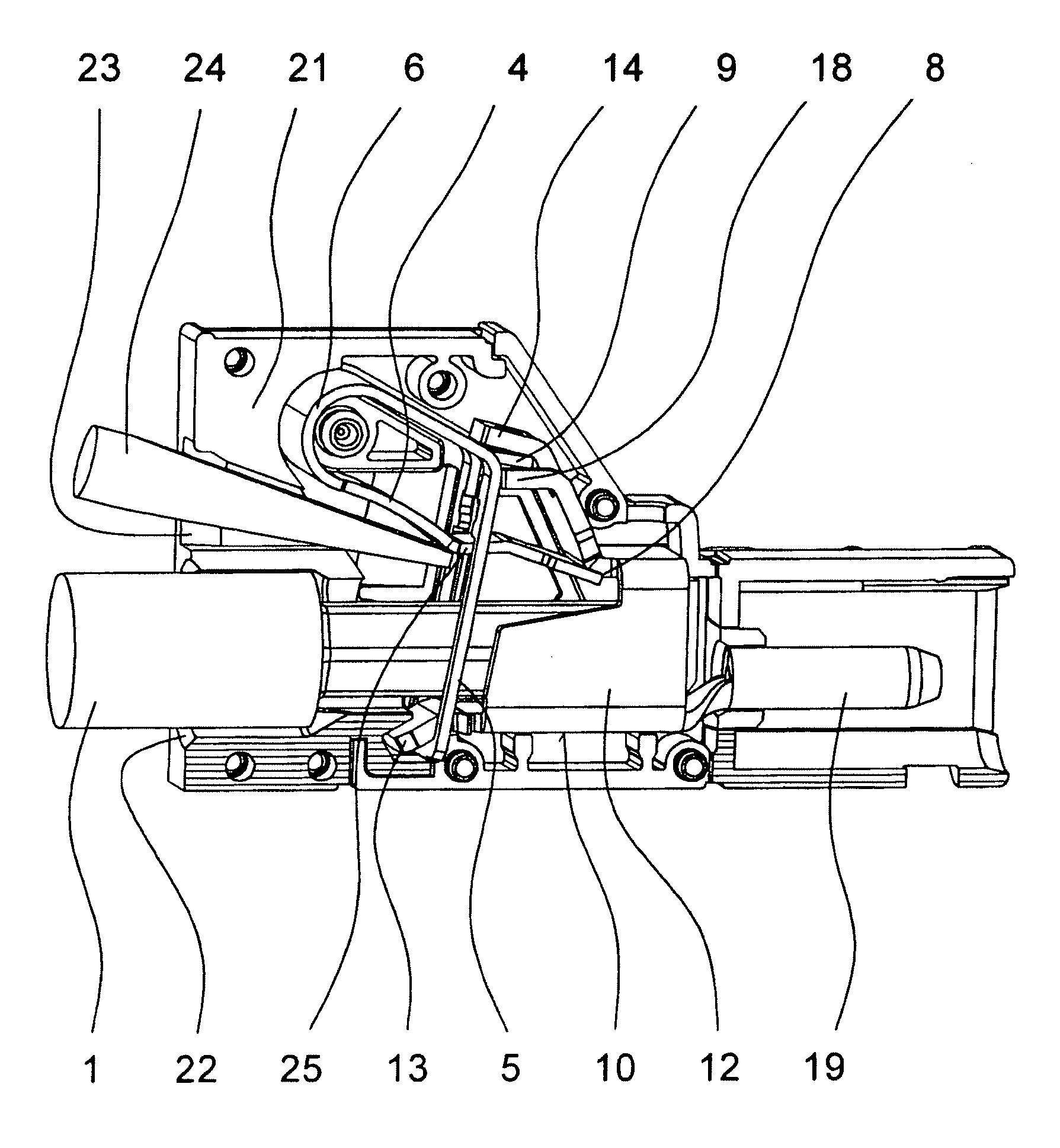
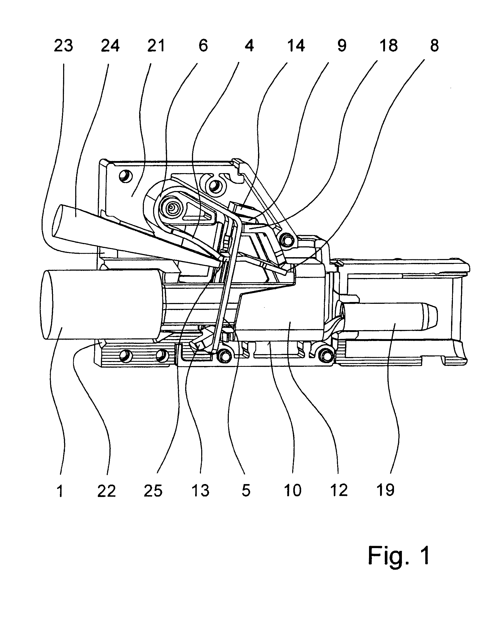
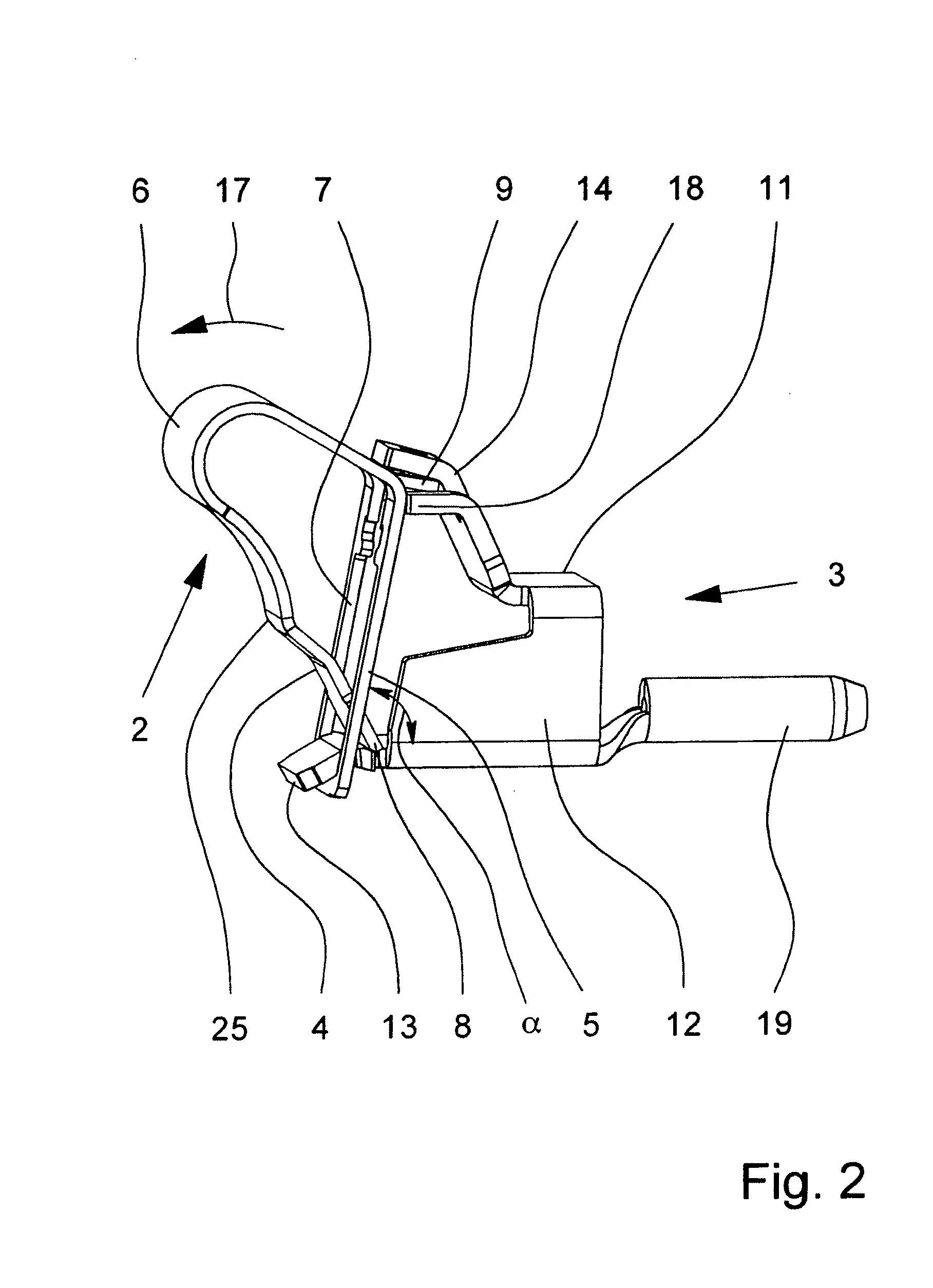
[0024]The figures show a connection clamp or terminal clamp for connection of an electrical conductor 1 which is shown only in FIG. 1. Important components of the connection clamp or terminal clamp are a clamp spring 2 and a metal part 3, in FIG. 3 the clamp spring 2 and the metal part 3 being shown in the not yet mounted state.

[0025]The clamp spring 2 is comprised of a clamp leg 4, a contact leg 5 and a back 6 which connects the clamp leg 4 and the contact leg 5. As is apparent from FIG. 1, the contact leg 5 of the clamp spring 2 is aligned essentially perpendicular to the insertion direction of the electrical conductor 1 to be connected. A recess 7 is formed in the contact leg 5 for inserting the conductor 1. On the end of the recess 7 which is away from the end 8 of the clamp leg 4, a retaining section 9 is punched out of the contact leg 5 and is bent essentially perpendicular to the contact leg 5 in the insertion direction of the electrical conductor 1 to be connected.

[0026]The ...


PUM


Abstract

An electric connection clamp or terminal clamp for connecting a terminal conductor has a clamp spring and a metal part. The clamp spring has a clamp limb and a contact limb, a recess for introducing the electric conductor being formed in said contact limb. The clamp limb and the contact limb are curved in such a manner that the end of the clamp limb penetrates through the recess. The end of the clamp limb and the contact limb form a spring force clamping connection for the conductor that is to be connected. The ends of the limbs each have a securing section and the securing section of the contact limb extends counter to the direction of introduction of the conductor through the recess.

Description

BACKGROUND OF THE INVENTION[0001]1. Field of Invention[0002]The invention relates to an electrical connection clamp or terminal clamp for connecting an electrical conductor, with a clamp spring and with a metal part, the clamp spring having one clamp leg and one contact leg, in the clamp leg a recess for insertion of the electrical conductor which is to be connected being made, the clamp leg and the contact leg of the clamp spring being bent to one another such that the end of the clamp leg is inserted through a recess, on the end of the recess which is away from the end of the clamp leg a retaining section being punched out of the contact leg and being bent in the insertion direction of the electrical conductor which is to be connected, the metal part having a contact leg, an opposite retaining leg and a bridge which connects the legs, the end of the clamp leg of the clamp spring and the contact leg of the metal part forming a spring force terminal connection for the electrical con...

Claims


Application Information

Patent Timeline
Patent Type & Authority Applications(United States)
IPC IPC(8): H01R4/48
CPCH01R13/04H01R4/4827H01R4/48275
Inventor HOPPE, UDO
Owner PHOENIX CONTACT GMBH & CO KG
Why Eureka
Try Eureka