Spinal Facet Fastener

a technology of spine and fastener, which is applied in the field of spine devices, can solve the problems of enlargement of joints, cartilage thinning or disappearing, wear or degeneration of many people, etc., and achieve the effect of preventing back-out and/or facet movemen

Active Publication Date: 2010-04-01
LIFE SPINE INC
View PDF58 Cites 42 Cited by
  • Summary
  • Abstract
  • Description
  • Claims
  • Application Information

AI Technical Summary

Benefits of technology

[0020]In one form of the spinal facet joint anchoring element, tabs thereof are configured to interact with the shaft of the tack to expand outward once the tack has been inserted into and about the spinal facet joint. This effectively wedges the anchoring element in place, further preventing back-out and / or facet movement.

Problems solved by technology

Facet joints are in almost constant motion with the spine and quite commonly simply wear out or become degenerated in many people.
When facet joints become worn or torn the cartilage may become thin or disappear and there may be a reaction of the bone of the joint underneath producing overgrowth of bone spurs and an enlargement of the joints.
Moreover, facet joints become especially vulnerable when the intervertebral disc is injured.
The flattening disc space provides much less support for the facet joints at that particular level, and the joints become subject to increased stress.

Method used


Image

  • Spinal Facet Fastener
  • Spinal Facet Fastener
  • Spinal Facet Fastener

Examples


Embodiment Construction

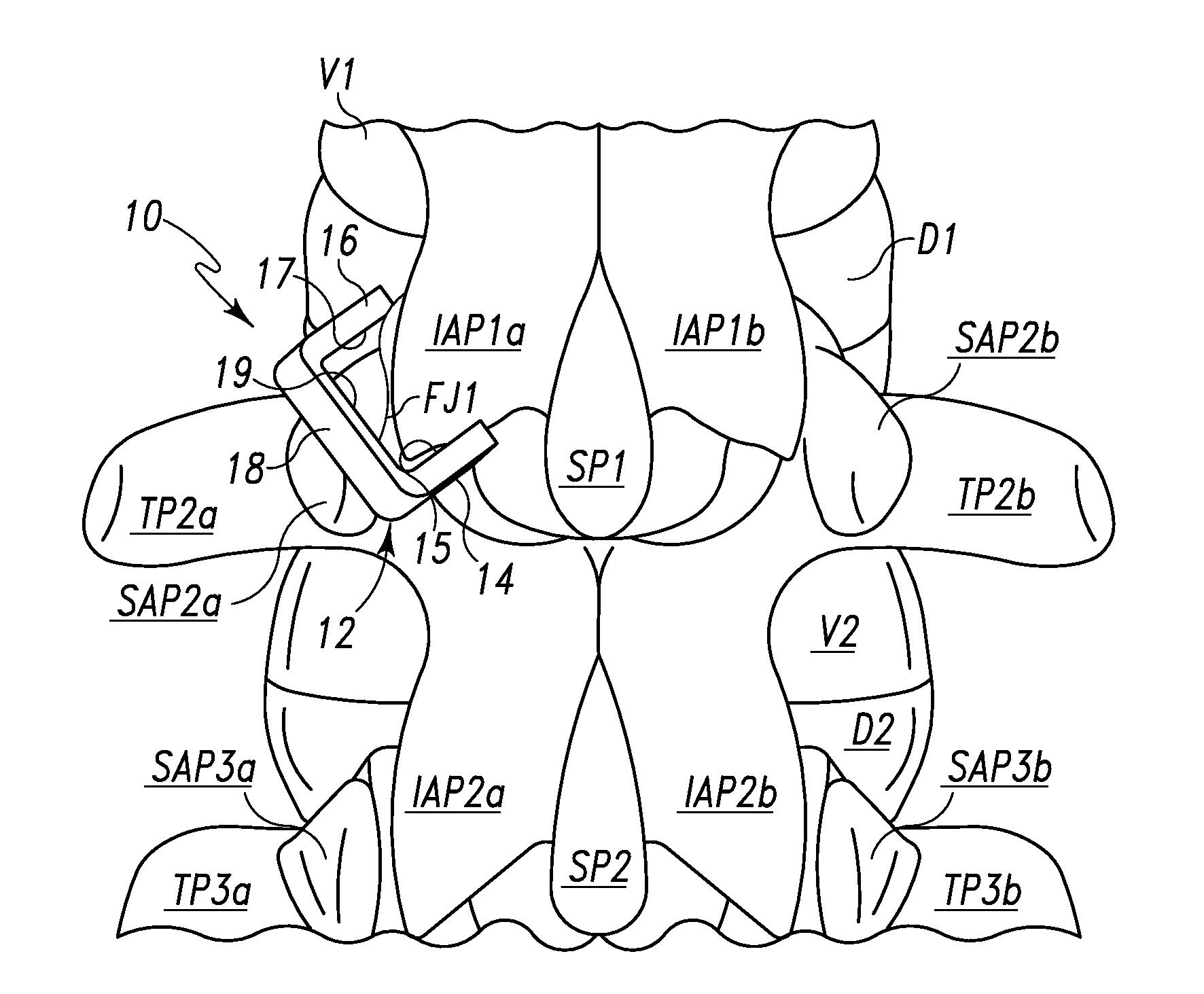
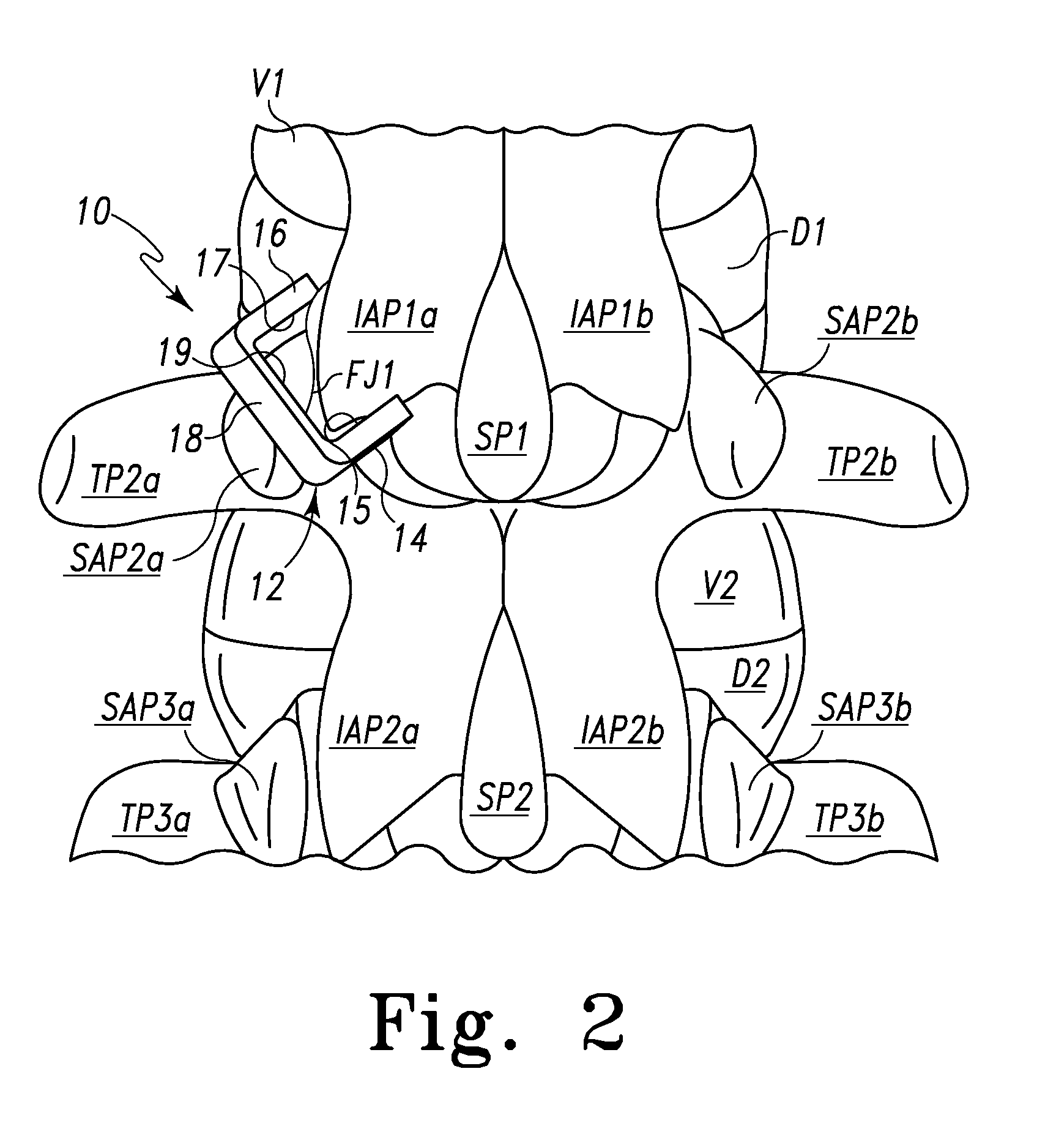
[0037]Referring to the figures, there is depicted various spinal facet fasteners fashioned in accordance with the present principles. The spinal facet fastener may be considered a clamp, tack, staple, retainer or holder depending on its form (hereinafter, collectively, spinal facet fastener). All of the spinal facet fasteners are fashioned from a biocompatible material such as plastic (e.g. polyetheretherketone (PEEK)), metal (e.g. titanium, stainless steel or alloy), a polymer, a composite, or the like.

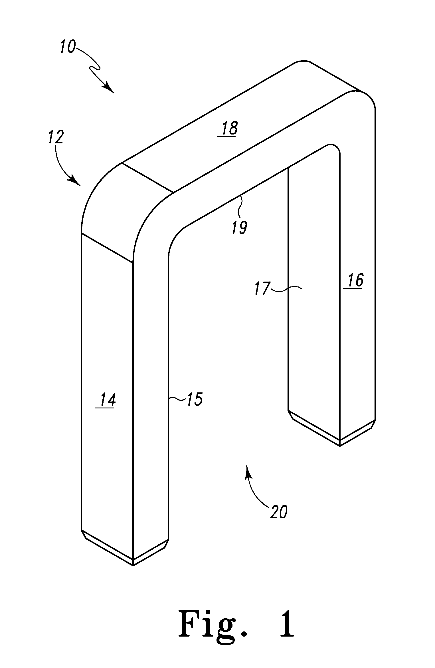
[0038]Referring particularly to FIG. 1, there is depicted a spinal facet fastener fashioned as a spinal facet clamp, generally designated 10. The spinal facet clamp 10 is characterized by a preferably, but not necessarily, unitary body 12. The body 12 has a first leg, member, post or the like 14 (collectively, leg 14), a second leg, member, post or the like 16 (collectively, leg 16) and a cross member 18 that all form a generally U-shaped body. It should be appreciated that the terms...


PUM


Abstract

A spinal implant in the form of a spinal facet fastener is configured to hold, restrict and/or limit flexion and/or extension of a spinal facet joint and/or immobilize movement thereof. The spinal facet fastener is formed with leg segments configured for reception in, on and/or about vertebral bone of a spinal facet joint and a connecting segment that holds the leg segments apart a spaced distance. The spinal facet fastener has surfaces that are configured to abut vertebral bone surfaces of a spinal facet joint to hold, restrict and/or limit flexion and/or extension of the spinal facet joint and/or immobilize movement thereof. In one form, the spinal facet fastener has members that are configured for reception in vertebral bone of the vertebral bone portions that form the spinal facet joint. In this form, the spinal facet fastener may include an anchoring element that is configured for reception between the vertebral bone portions that form the spinal facet joint. In one form, a first leg is configured to abut a surface of an inferior articular process of a first vertebra while a second leg is configured to abut a surface of a superior articular process of a second vertebra that is adjacent the first vertebra. The spinal facet fastener is formed of a biocompatible material such as PEEK (polyetheretherketone) but may be formed of other biocompatible materials such as a biocompatible metal (e.g. titanium or stainless steel).

Description

RELATED APPLICATIONS[0001]This patent application claims the benefit of and / or priority to U.S. Provisional Patent Application Ser. No. 61 / 101,800 filed Oct. 1, 2008, entitled “Spinal Facet Fastener” the entire contents of which is specifically incorporated herein by this reference.BACKGROUND OF THE INVENTION[0002]1. Field of the Invention[0003]The present invention relates to devices for the spine and, more particularly, to devices for restricting, limiting and / or stopping motion between adjacent vertebrae.[0004]2. Background Information[0005]As we age various changes can occur in the body especially with respect to the spinal column or spine. For instance, the ligaments of the spine can thicken and calcify (i.e. harden from deposits of calcium), bone and joints may enlarge, bone spurs called osteophytes may form, spinal discs may break down, collapse, bulge and / or herniate. Moreover, one vertebra may slip over another vertebra (spondylolisthesis). Facet joints of the spine can als...

Claims


Application Information

Patent Timeline
Patent Type & Authority Applications(United States)
IPC IPC(8): A61B17/70
CPCA61B17/7064
Inventor BUTLER, MICHAEL S.HARTSELL, BRIAN D.
Owner LIFE SPINE INC
Why Eureka
Try Eureka