Bone Screw Implant for Sacroiliac Joint Fusion

Active Publication Date: 2019-12-26
LIFE SPINE INC
View PDF0 Cites 10 Cited by
  • Summary
  • Abstract
  • Description
  • Claims
  • Application Information

AI Technical Summary

Benefits of technology

The patent text describes a device used in orthopedic surgery that helps prevent the bone screw from coming out of the bone. The device is a sleeve that is securely attached to the bone screw and can rotate with it. The sleeve is designed to be pushed into the bone while the bone screw is being inserted, and a set screw is used to lock the two components together, preventing the screw from coming out. The bone screw also has cutting tips that allow the surgeon to drill the bone without needing to make separate steps in the operation. Overall, this device improves the stability and speed of orthopedic surgery procedures.

Problems solved by technology

However, no matter where bone screws are used, they face challenges of “backing out” of the anatomy in which they are installed.
Bone screw malfunction such as backing out can compromise the integrity of the orthopedic purpose for which the bone screws were installed and / or pose serious risks and / or complications for the implant recipient.

Method used


Image

  • Bone Screw Implant for Sacroiliac Joint Fusion
  • Bone Screw Implant for Sacroiliac Joint Fusion
  • Bone Screw Implant for Sacroiliac Joint Fusion

Examples


Embodiment Construction

[0044]For the purposes of promoting an understanding of the principles of the present disclosure, reference will now be made to the embodiments illustrated in the drawings, and specific language will be used to describe the same. It will nevertheless be understood that no limitation of the scope of this database is thereby intended.

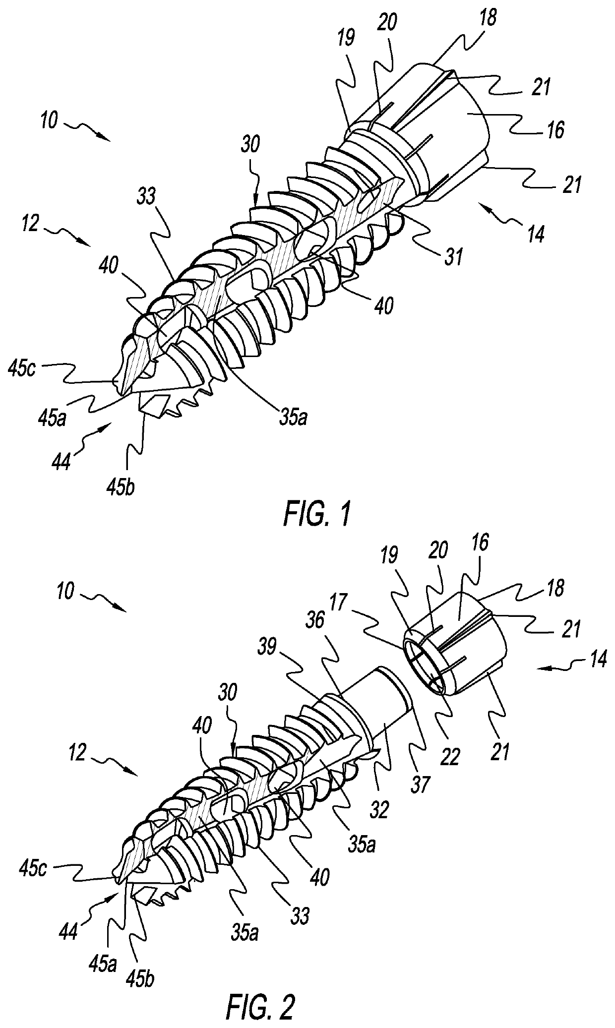
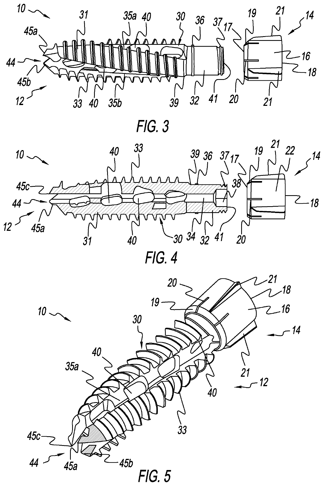
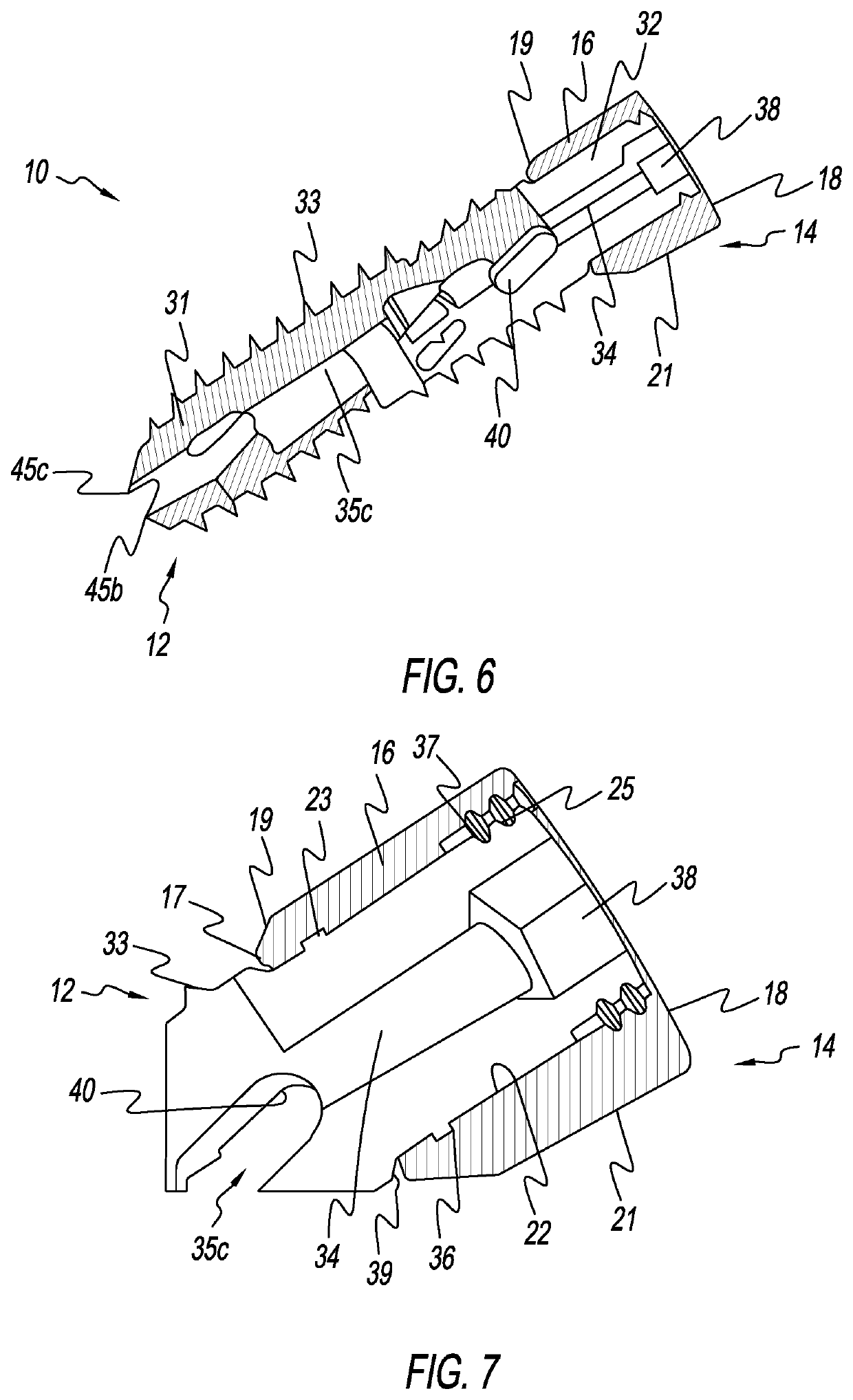
[0045]FIGS. 1-7 depict various exploded and non-exploded views of a bone screw implant 10 fashioned in accordance with the present principles, characterized by a bone screw 12 and a sleeve 14. FIGS. 11 and 15-20 depict various views of the bone screw 12. FIGS. 8-10 depict various views of the sleeve 14, while FIGS. 12-14 depict various views of an alternate sleeve 14a. The bone screw implant 10 is best used for sacroiliac fusion, but may be used for various spine applications as well as other orthopedic applications.

[0046]The bone screw 12 is characterized by a body 30 having a self-drilling or self-tapping tip 44 at its distal end and may include externa...


PUM


Abstract

A bone screw for sacroiliac joint fusion is characterized by a longitudinal bone screw and a cylindrical sleeve received on a proximal end of the bone screw. The sleeve has axially extending fins or flutes on its outer surface that extend generally from one end of the sleeve to the other end of the sleeve. This feature allows the sleeve to resist reverse rotation which, in turn, aids in preventing back-out of the bone screw once installed. The bone screw has a self-tapping tip that allows the bone screw to be installed without need for a pilot hole, and self-harvesting geometry that gathers and retains bone shavings in and along the bone screw that are produced by bone screw installation for use as graft for bone fusion.

Description

CROSS-REFERENCE TO RELATED APPLICATIONS[0001]This U.S. non-provisional patent application claims the benefit of and / or priority under 35 U.S.C. § 119(e) to U.S. provisional patent application Ser. No. 62 / 687,339 filed Jun. 20, 2018 titled “Bone Screw Implant for Sacroiliac Joint Fusion” the entire contents of which is specifically incorporated herein by reference.FIELD OF THE INVENTION[0002]The present invention relates to bone screws for the spine and related anatomy and, more particularly, to bone screws for sacroiliac joint fusion and related anatomy.BACKGROUND OF THE INVENTION[0003]Bone screws are used routinely for repairing, stabilizing, fixing, fusing and other orthopedic purposes of bones of the body such as the spine and pelvis. However, no matter where bone screws are used, they face challenges of “backing out” of the anatomy in which they are installed. Bone screw malfunction such as backing out can compromise the integrity of the orthopedic purpose for which the bone scr...

Claims


Application Information

Patent Timeline
IPC IPC(8): A61B17/86A61B17/70
CPCA61F2002/30995A61B17/7055A61B17/7001A61F2002/30622A61F2/28A61F2/4455A61B17/86A61B17/1671A61B17/8605A61B17/8625A61B17/8635A61B17/864A61B2017/8655A61B17/8685A61B17/863A61B17/1635
Inventor MEHL, DAVID T.MESIWALA, ALI H.
Owner LIFE SPINE INC
Why Eureka
Try Eureka