
Folding Tube

Inactive Publication Date: 2010-04-08
KARDACH GERALD E
View PDF13 Cites 2 Cited by
  • Summary
  • Abstract
  • Description
  • Claims
  • Application Information

AI Technical Summary

Benefits of technology

[0022]The present invention is a dispensing tube made from a single machining process, which utilizes novel tooling to create interlocking components directly on the existing surface of a toothpaste tube. In other embodiments, various interlocking and clip-on components may be utilized to create a dispensing tube that more efficiently extracts a viscous substance as the tube empties.

Problems solved by technology

Although Rodder '349 teaches a method and apparatus for compacting the expended portion of a tube, this apparatus also requires separately manufactured components and is un-hygienic because hair, dust, lint and other bacterial substances are attracted to an adhesive surface.
In addition, it requires that the adhesive be attached to the tube after manufacturing and requires the user to subsequently remove segments of liner-from the adhesive strip which limits the locations where the tube can be folded.

Method used


Image

  • Folding Tube
  • Folding Tube
  • Folding Tube

Examples


Embodiment Construction

[0023]For the purpose of promoting an understanding of the present invention, references are made in the text to exemplary embodiments of a dispensing tube with interlocking components, only some of which are described herein. It should be understood that no limitations on the scope of the invention are intended by describing these exemplary embodiments. One of ordinary skill in the art will readily appreciate that alternate but functionally equivalent shapes, materials and mechanisms may be used. The inclusion of additional elements may be deemed readily apparent and obvious to one of ordinary skill in the art. Specific elements disclosed herein are not to be interpreted as limiting, but rather as a basis for the claims and as a representative basis for teaching one of ordinary skill in the art to employ the present invention.

[0024]It should be understood that the drawings are not necessarily to scale; instead, emphasis has been placed upon illustrating the principles of the invent...


PUM

PropertyMeasurementUnit
Distanceaaaaaaaaaa
Distanceaaaaaaaaaa
Viscosityaaaaaaaaaa

Abstract

The present invention is a dispensing tube made from a single machining process, which utilizes novel tooling to create interlocking components directly on the existing surface of a toothpaste tube. In other embodiments, various interlocking and clip-on components may be utilized to create a dispensing tube that more efficiently extracts a viscous substance as the tube empties.

Description

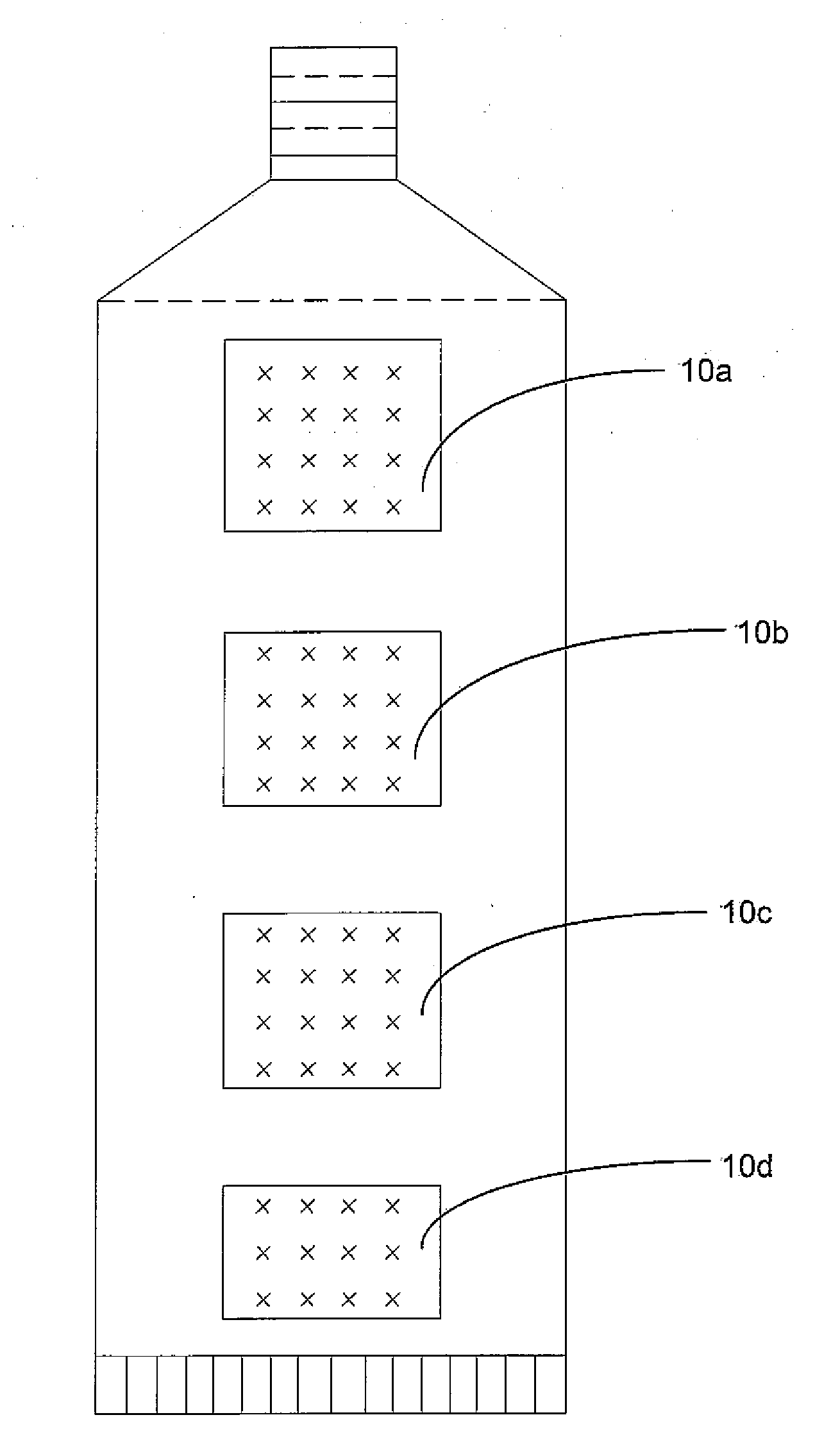
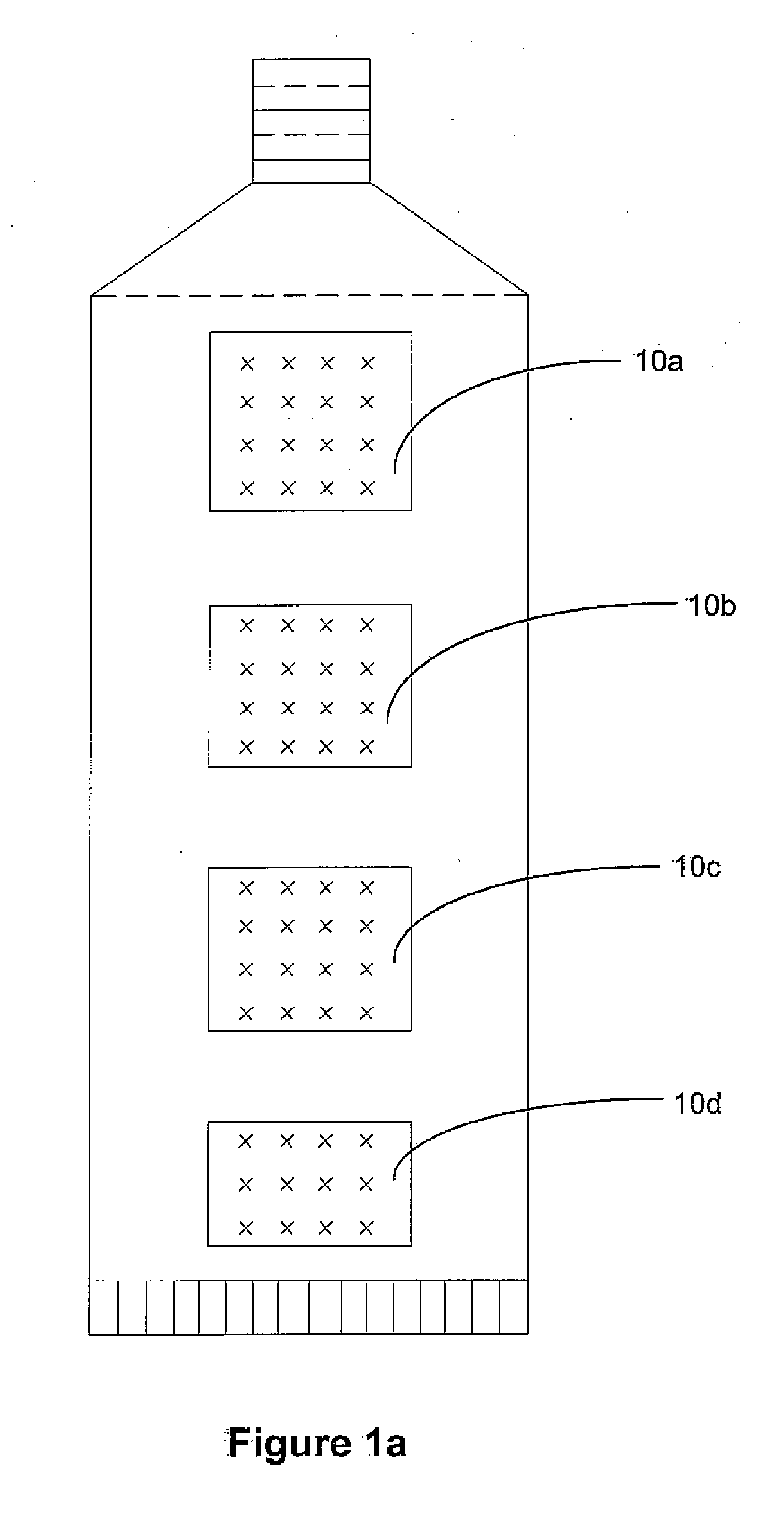
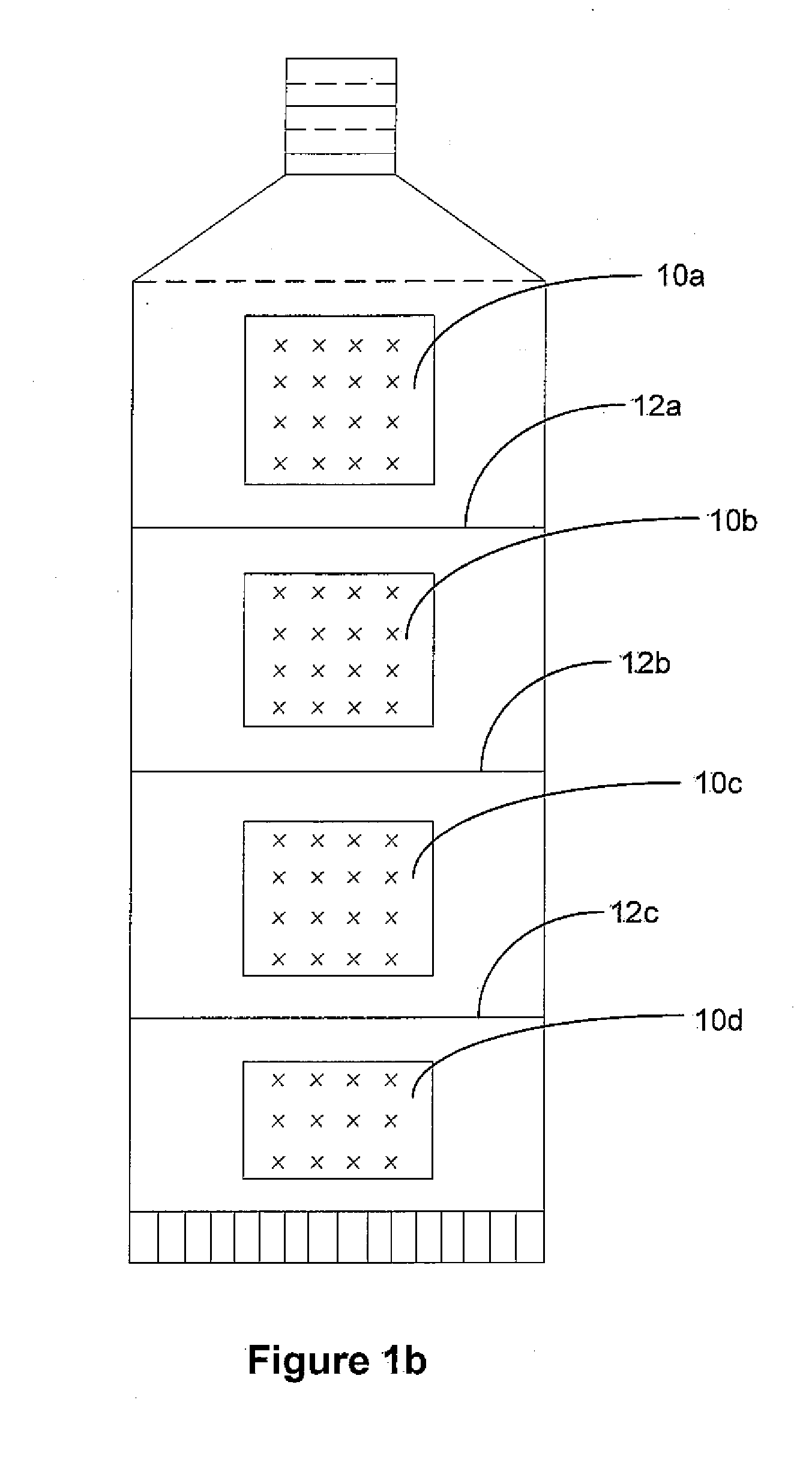
CROSS-REFERENCE TO RELATED APPLICATIONS[0001]This application claims priority to U.S. Provisional Application No.[0002]61 / 195,063 filed on Oct. 3, 2008.FIELD OF INVENTION[0003]The present invention relates to dispensing tubes and more particularly to structural components for folding the tubes and squeezing out the material to be dispensed.BRIEF DESCRIPTION OF THE DRAWINGS[0004]FIG. 1a illustrates atop perspective view of an exemplary embodiment of a dispensing tube having textured sections which are integrally manufactured with the dispensing tube.[0005]FIG. 1b illustrates a top perspective view of an exemplary embodiment of dispensing tube having including textured sections and scoring to facilitate the interlocking of textured sections.[0006]FIG. 1c illustrates a top perspective view of a dispensing tube having textured sections and scoring engaged in a folded position.[0007]FIG. 2a illustrates a side perspective view of an exemplary embodiment of first interlocking surface and s...

Claims


Application Information

Patent Timeline
IPC IPC(8): B65D35/02B23P17/04
CPCB65D35/24B65D35/18
Inventor KARDACH, GERALD E.
Owner KARDACH GERALD E
Learn More