Hydroelectric power plant and method of generating power

Inactive Publication Date: 2007-09-20
HYDRO INNOVATION CORP
View PDF21 Cites 1 Cited by
  • Summary
  • Abstract
  • Description
  • Claims
  • Application Information

AI Technical Summary

Benefits of technology

[0003] One problem with the former solution is that power is most efficiently extracted from moving water by not having to stop and then re-accelerate the water. One problem with the latter solution is

Problems solved by technology

One problem with the former solution is that power is most efficiently extracted from moving water by not having to stop and then re-accelerate the water.
One

Method used


Image

  • Hydroelectric power plant and method of generating power
  • Hydroelectric power plant and method of generating power
  • Hydroelectric power plant and method of generating power

Examples


Example

[0029] In the following description, the use of “a,”“an,” or “the” can refer to the plural. All examples given are for clarification only, and are not intended to limit the scope of the invention.

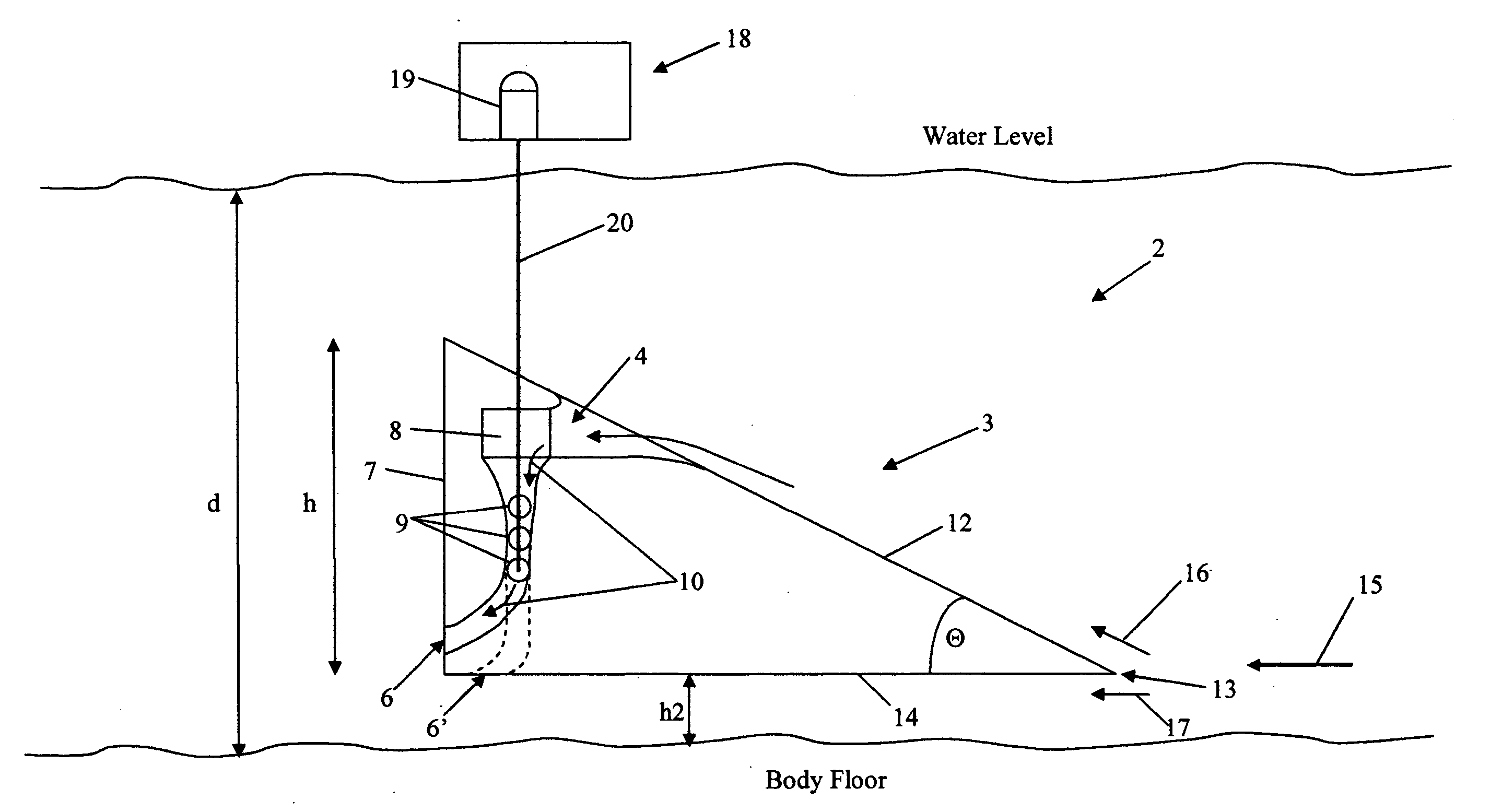
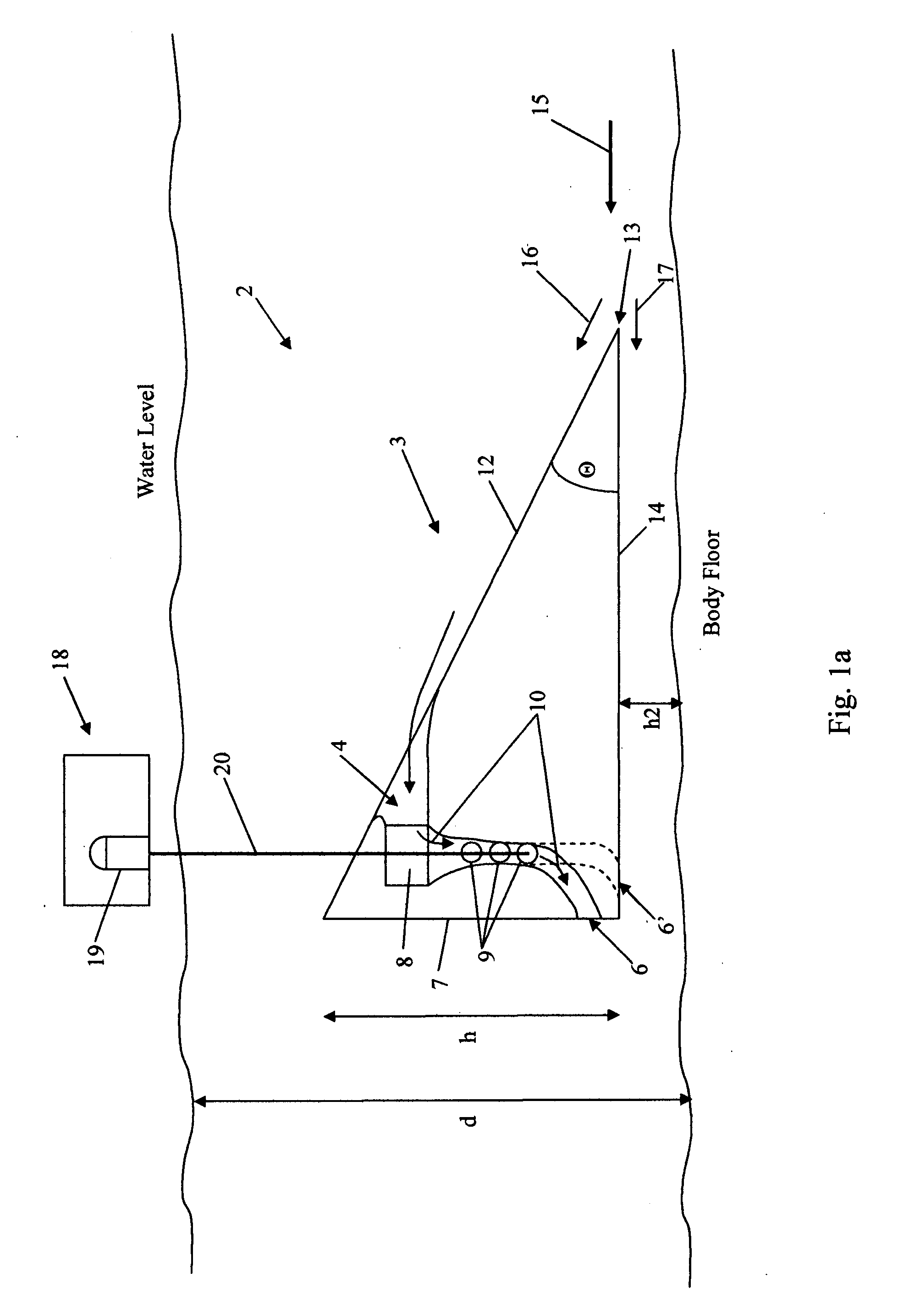
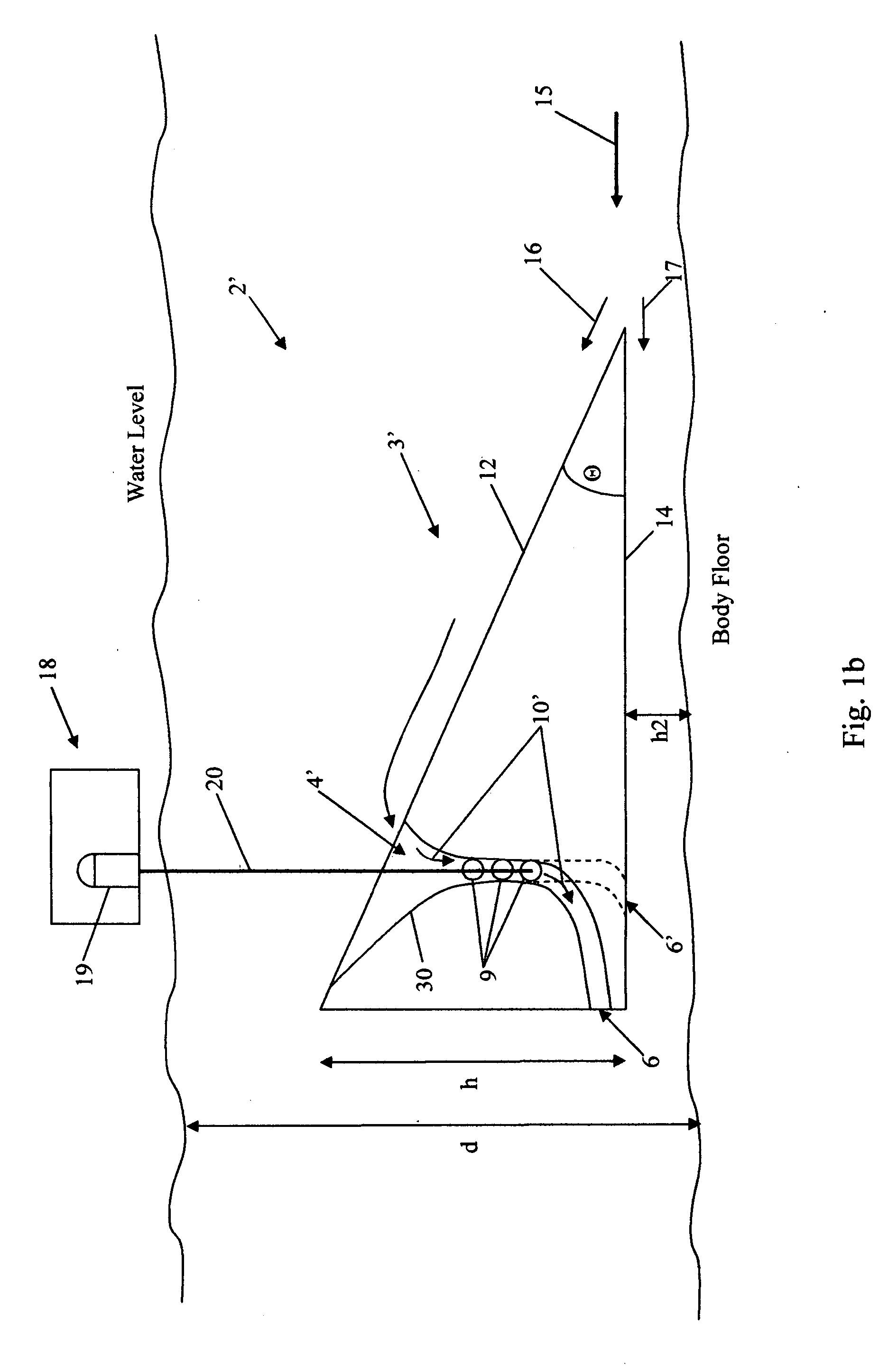
[0030] Referring now to FIG. 1a, a power plant 2 comprises a wedge 3 connected to a generating station 18 via a shaft 20. The generating station 18 includes at least one electrical generator 19, such as a generator that converts rotational energy to electricity, as known in the art. The wedge 3 is located within a body of water having a Body Floor and a Water Level, and comprises an upper surface 12 and a lower surface 14, the surfaces 12, 14 angled with respect to each other by angle Θ. The body of water has a current having a fluid flow 15. The angle Θ may be at least approximately 15°, preferably ranges from approximately 30 to 60°, and more preferably ranges from approximately 40 to 50°. The upper surface 12 may be adjustable with respect to the lower surface 14 so that the angle Θ can...


PUM


Abstract

A hydroelectric power plant includes a wedge having a fluid intake, and a fluid engine located in a fluid path between the fluid intake and a fluid exhaust. The wedge may include at least upper and lower surfaces, the upper and lower surfaces angled with respect to each other by at least approximately 15°, and the wedge may be shaped to receive a fluid flow in the fluid intake.

Description

REFERENCE TO RELATED APPLICATIONS [0001] The present application is a Continuation-in-Part of U.S. patent application Ser. No. 11 / 348,604, filed Feb. 7, 2006, entitled, “Hydroelectric Power Plant and Method of Generating Power,” the disclosure of which is hereby incorporated by reference.BACKGROUND [0002] Power is often extracted from moving water by either damming the water (i.e., effectively stopping the water) and taking advantage of a flow of water downward from the dam, or by using a turbine within a water flow. SUMMARY OF THE INVENTION [0003] One problem with the former solution is that power is most efficiently extracted from moving water by not having to stop and then re-accelerate the water. One problem with the latter solution is that harsh water environments (such as silt, mud, salt, etc.) often cause fouling and regular maintenance of the turbines. The present invention aims to solve at least one of these and other problems. [0004] In one embodiment, a hydroelectric powe...

Claims


Application Information

Patent Timeline
IPC IPC(8): F04D27/02
CPCF03B17/06Y02E10/28F05B2240/13Y02E10/30Y02E10/20
Inventor CRESCI, TIMOTHY
Owner HYDRO INNOVATION CORP
Why Eureka
Try Eureka