Tapered guide bushing for reciprocating driver and tool incorporating same

Active Publication Date: 2010-04-08
POWERNAIL
View PDF58 Cites 23 Cited by
  • Summary
  • Abstract
  • Description
  • Claims
  • Application Information

AI Technical Summary

Problems solved by technology

The previously known mechanisms for power driving have been of substantial size and weight and dimensionally unsuited for operation in confined areas.
Such mechanisms also have primarily incorporated the principle of a single stroke operation, controllable at the desire or will of an operator, and have not normally been adapted for use where relatively short repetitive strokes of a tool or operating mechanism are desirable.
These compact impact tools can be used in compact areas, but have neglected to address the

Method used


Image

  • Tapered guide bushing for reciprocating driver and tool incorporating same
  • Tapered guide bushing for reciprocating driver and tool incorporating same
  • Tapered guide bushing for reciprocating driver and tool incorporating same

Examples


first embodiment

and 5

[0029]FIG. 5A is an enlarged exploded perspective view of a tapered guide bushing assembly of FIG. 5.

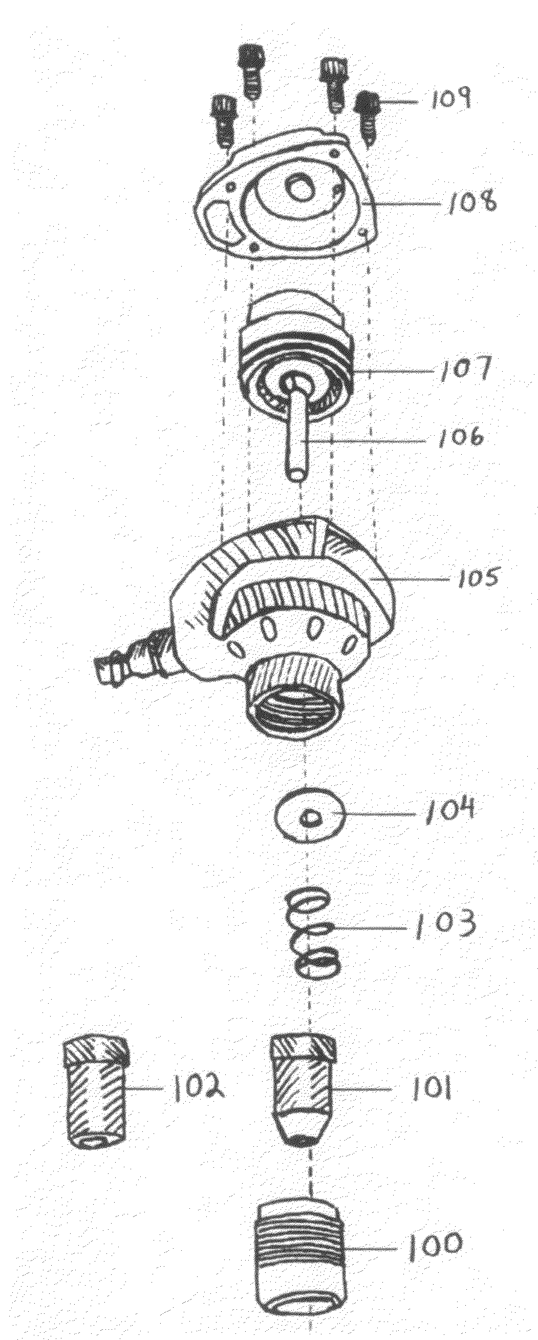
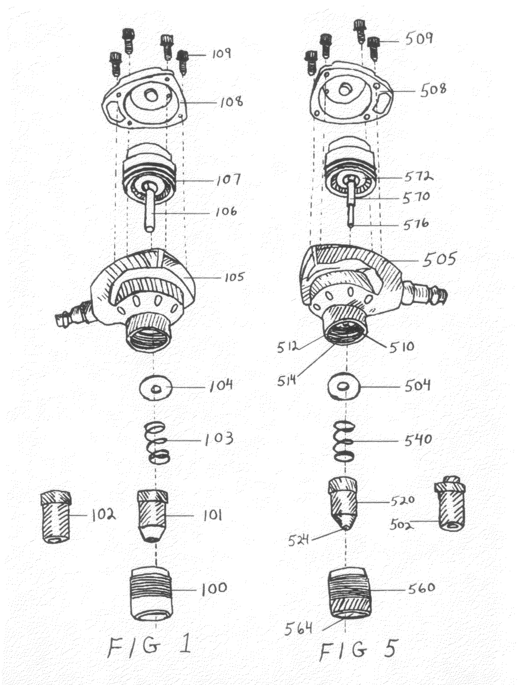
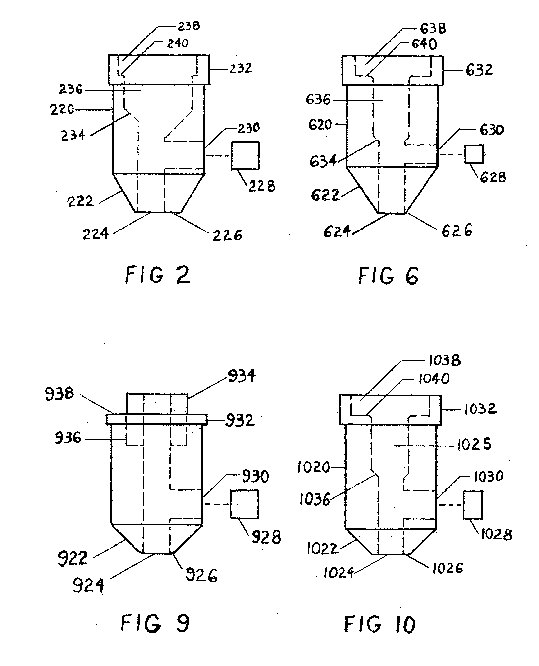
[0030]FIG. 5A shows a guide bushing 520 has a taper 522 to a sharp edge tip 526. A magnet 528 is adhered in a perpendicular bore 530 to a guide bushing bore 524. The guide bushing 520 has a stepped center bore 536 forming a shoulder 534 which is congruent in shape to a driver rod 570 with a shoulder 544. The driver rod 570 is guided by the guide bushing bore 524. The guide bushing 520 has a stepped bore 538 forming a spring seat 539. The guide bushing has a peripheral collar 532 which is slide mounted into a removable guide sleeve securing collar 560 and thereon adapted for engagement with a circular abutment 562 formed in the interior bore 564 of the securing collar 560. The driver rod 570 is threaded into FIG. 5 a piston 572. FIG. 5 shows the piston 572 attached to the driver rod 570 showing a removable assembly 570 and 572 is encased in both a lower housing 505 and upper hous...


PUM


Abstract

A guide bushing for a reciprocating nailer includes a body having a cylindrical portion and a tapered portion. An aperture extends through the body for receiving a driving rod. The tapered portion of the guide bushing extends from the nailer and is configured to fit into tight spaces, such as corners and along the tongues or grooves of, for instance, tongue and groove flooring, to fully support a nailer as it is driven into the tight space. The guide bushing can be a multiple part or multiple stage bushing for more flexibility and utility. The aperture through the center of the bushing can also be stepped to cooperate with a stepped driving rod for closer holding of narrower nails. A boot can be placed at the tip of the guide bushing to provide a cushion and further retention of a nail held by the nailer.

Description

CROSS-REFERENCE TO RELATED APPLICATIONS[0001]This application claims the benefit of provisional patent application Ser. No. 61 / 081,062, filed Jul. 16, 2008 by the present inventor.BACKGROUND[0002]1. Field[0003]This application relates to a compact, reciprocating, electrically or pneumatically operated impact tool, and specifically to an improved nail guide bushing mechanism for palm nailers.[0004]2. Prior Art[0005]The previously known mechanisms for power driving have been of substantial size and weight and dimensionally unsuited for operation in confined areas. Such mechanisms also have primarily incorporated the principle of a single stroke operation, controllable at the desire or will of an operator, and have not normally been adapted for use where relatively short repetitive strokes of a tool or operating mechanism are desirable.[0006]Compact reciprocating impact tools, which are electrically or pneumatically operated (Hammerhead auto hammer, palm nailer) have overcome the drawb...

Claims


Application Information

Patent Timeline
IPC IPC(8): B25C1/04
CPCB25C1/00
Inventor ABLA, KEITH DANIEL
Owner POWERNAIL
Why Eureka
Try Eureka