Enclosures for Light Sources

a technology for enclosures and light sources, applied in semiconductor devices, light source lighting support devices, lighting and heating devices, etc., can solve problems such as complicated construction of such fixtures

Inactive Publication Date: 2010-04-08
ABL IP HLDG
View PDF6 Cites 38 Cited by
  • Summary
  • Abstract
  • Description
  • Claims
  • Application Information

AI Technical Summary

Problems solved by technology

In fact, the hazardous voltage-producing circuitry of the LEDs has traditionally been enclosed within multiple layers of metal, glass, or potting compound, greatly complicating the construction of such fixtures.

Method used


Image

  • Enclosures for Light Sources
  • Enclosures for Light Sources
  • Enclosures for Light Sources

Examples


Embodiment Construction

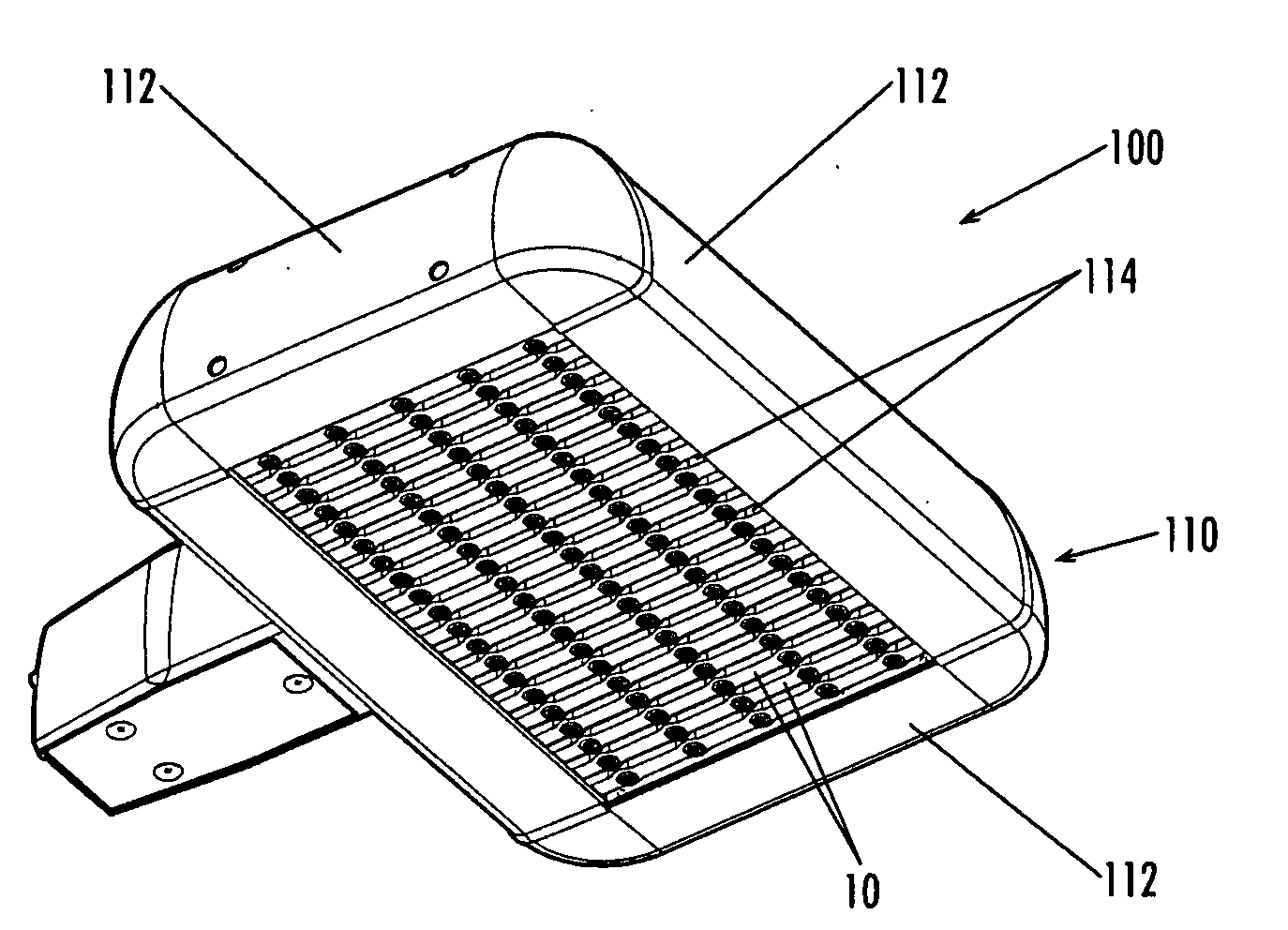
[0010]Embodiments of this invention provide enclosures for protecting light sources from environmental elements while meeting various safety and manufacturing regulations. The enclosure encapsulates the electrical and light producing components in a single body in an acceptable material, protecting them from the environment while allowing light to escape from the enclosure.

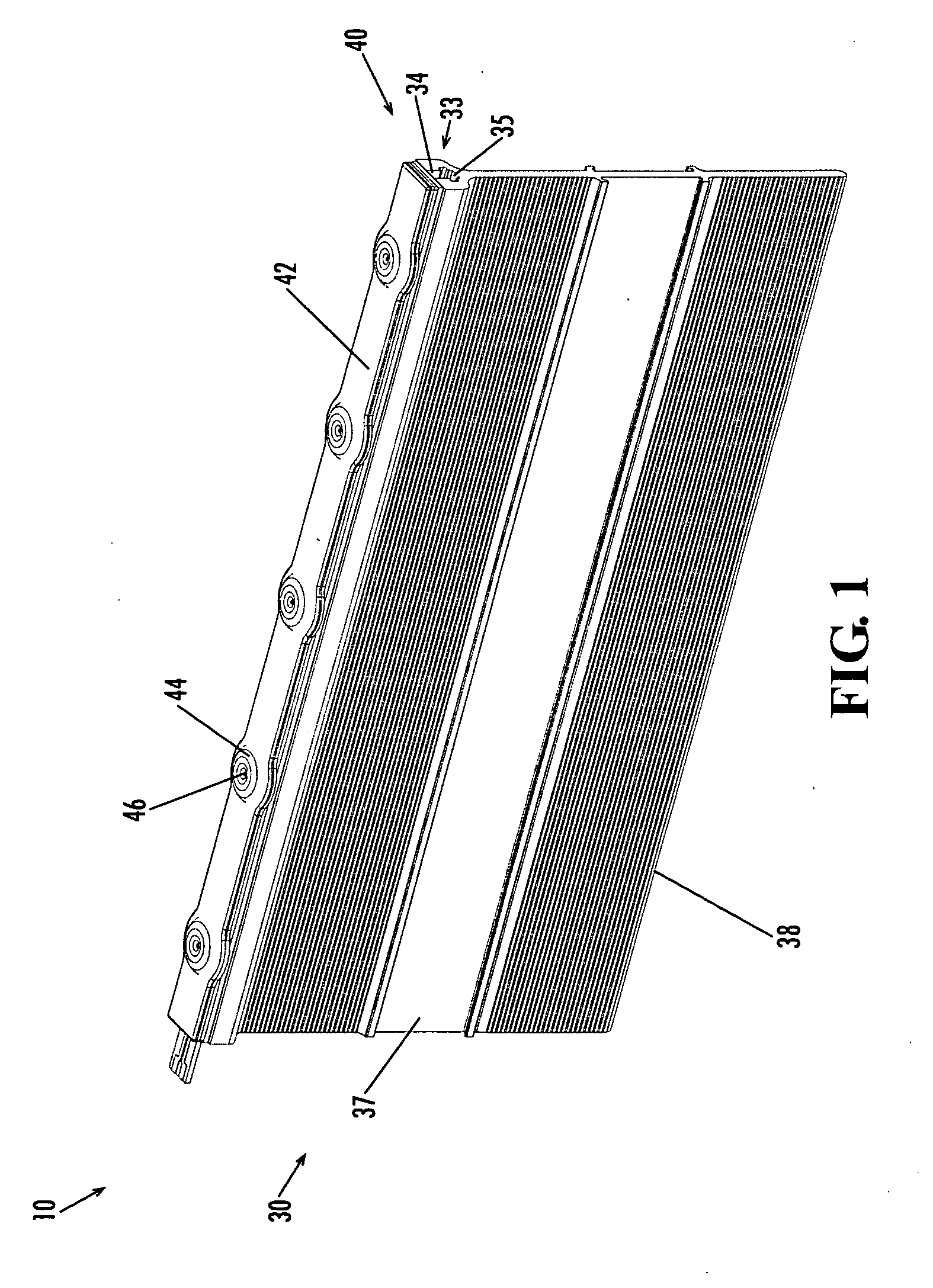
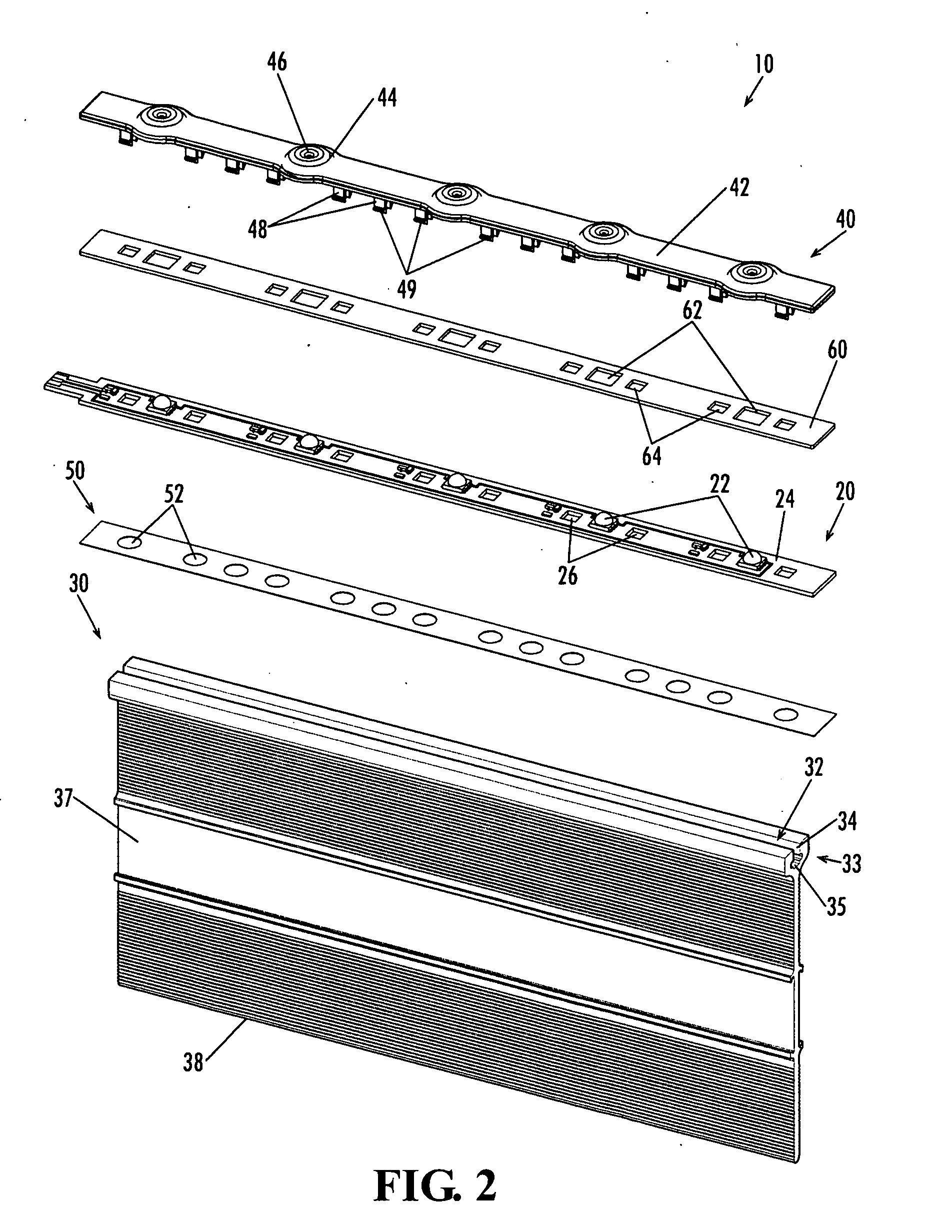
[0011]FIGS. 1-2 illustrate an enclosure 10 according to one embodiment of this invention. The enclosure 10 contains both the light source and the light source's electrical components, eliminating the need for two separate enclosures. The enclosure 10 includes a light source 20 enclosed between a support structure 30 and an enclosure cover 40. The light source 20 as shown in FIG. 2 includes light emitting diodes (“LEDs”) 22. Note, however, that other light fixtures may use other types of light sources and is not limited to use with only LEDs 22. Light sources such as, but not limited to, organic LEDs, incandescents...


PUM


Abstract

Embodiments of the present invention provide enclosures for light sources, such as, but not limited to, LEDs, and their circuitry that obviate the need for separate enclosures. The light sources and their circuitry are mounted on a support structure that serves as a heat sink and protected from the environment by a flame resistant and partially transparent protective cover. Multiple such enclosures may be used in a light fixture.

Description

CROSS REFERENCE TO RELATED APPLICATION[0001]This application claims the benefit of U.S. provisional application Ser. No. 61 / 039,647, entitled “LED Enclosure and Area Light” and filed Mar. 26, 2008, the entire contents of which are hereby incorporated by this reference.FIELD OF INVENTION[0002]The invention is directed to enclosures for light sources and lighting fixtures that use such enclosures.BACKGROUND OF INVENTION[0003]Light fixtures covering large areas are well known in the art. Such light fixtures used in outdoor applications are continuously exposed to the elements and must be able to withstand such exposure. These light fixtures must be able to protect the electrical components while allowing the light to be adequately emitted from the fixture. Many traditional outdoor light fixtures employ a housing that surrounds and protects all components of the light fixture. For safety concerns, all the components of the light fixture must be enclosed according to such standard settin...

Claims


Application Information

Patent Timeline
Patent Type & Authority Applications(United States)
IPC IPC(8): F21S4/00F21V17/00F21V29/00
CPCF21K9/00F21V15/01F21V29/004F21W2131/10F21Y2101/02F21V29/89F21Y2103/003F21V31/005F21V29/20F21V29/83F21K9/30F21V5/04F21V29/70F21K9/20F21K9/69F21Y2103/10F21Y2115/10
Inventor SHANER, JEFF
Owner ABL IP HLDG
Why Eureka
Try Eureka