
Radiant energy conversion system

a technology of conversion system and radiation energy, which is applied in the direction of thermal-pv hybrid energy generation, instruments, and domestic cooling apparatus, etc., can solve the problems of inability to justify system cost, inability to achieve one-axis tracking, and severe shortage of solar panels

Inactive Publication Date: 2010-12-28
INLAND MARINE IND +1
View PDF27 Cites 40 Cited by
  • Summary
  • Abstract
  • Description
  • Claims
  • Application Information

AI Technical Summary

Benefits of technology

"The present invention describes various techniques for converting radiant energy. One aspect is to provide a solar energy converter in a flat panel profile with high conversion efficiency and lower usage of PV materials. Another aspect is to design a tracking mechanism that can withstand harsh environments without maintenance, achieving low cost and family friendliness. Another aspect is to produce a panel design easily adaptable to high volume, low cost manufacturing processes. Another aspect is to enable the appearance of any color as desired by consumers without loss of efficiency to broaden the adoption of solar technology. Another aspect is to design an apparatus that can collimate, combine and project the emission from an array of light emitting diodes towards a desired direction. Another aspect is to provide a system that can collimate, combine and project the emission from an array of light emitting diodes towards a desired direction. The invention has various functions and means to achieve these technical effects."

Problems solved by technology

The supply of solar panels, dominated by polycrystalline silicon technology, is in severe shortage due to limited PV material supplies.
At concentration ratio over 100, one-axis tracking is not practical, as it would require manual adjustments every few days.
One axis tracking with seasonal adjustment is limited to lower concentrations, which do not justify system cost.
Due to the harsh environment in the field, such as, but not limited to, wind, rain, dust and temperature cycles, the concentrator systems have to be made bulky and complex, and are therefore expensive to build, install, and maintain.
Because of the bulky construction and complexity in maintenance, they are long believed to be unfit and unsightly for commercial or residential applications, especially for rooftop of homes.
For utility installations, commonly thought of as the major application of CPV, the complexity and perceived risks under severe weather conditions made the acceptance of these flat plate CPV modules challenging.
Attempts to lower the cost of ownership by reducing system size and minimizing impact of the environment were unsuccessful.
As a result, concentrator PV systems have failed to reach commercial success beyond demonstration projects.
For residential applications, the dark appearance of the conventional solar panels is unacceptable to some.

Method used


Image

  • Radiant energy conversion system
  • Radiant energy conversion system
  • Radiant energy conversion system

Examples


Embodiment Construction

[0020]The present invention is best understood by reference to the detailed figures and description set forth herein.

[0021]Embodiments of the invention are discussed below with reference to the Figures. However, those skilled in the art will readily appreciate that the detailed description given herein with respect to these figures is for explanatory purposes as the invention extends beyond these limited embodiments. For example, it should be appreciated that those skilled in the art will, in light of the teachings of the present invention, recognized a multiplicity of alternate and suitable approaches, depending upon the needs of the particular application, to implement the functionality of any given detail described herein, beyond the particular implementation choices in the following embodiments described and shown. That is, there are numerous modifications and variations of the invention that are too numerous to be listed but that all fit within the scope of the invention. Also,...


PUM


Abstract

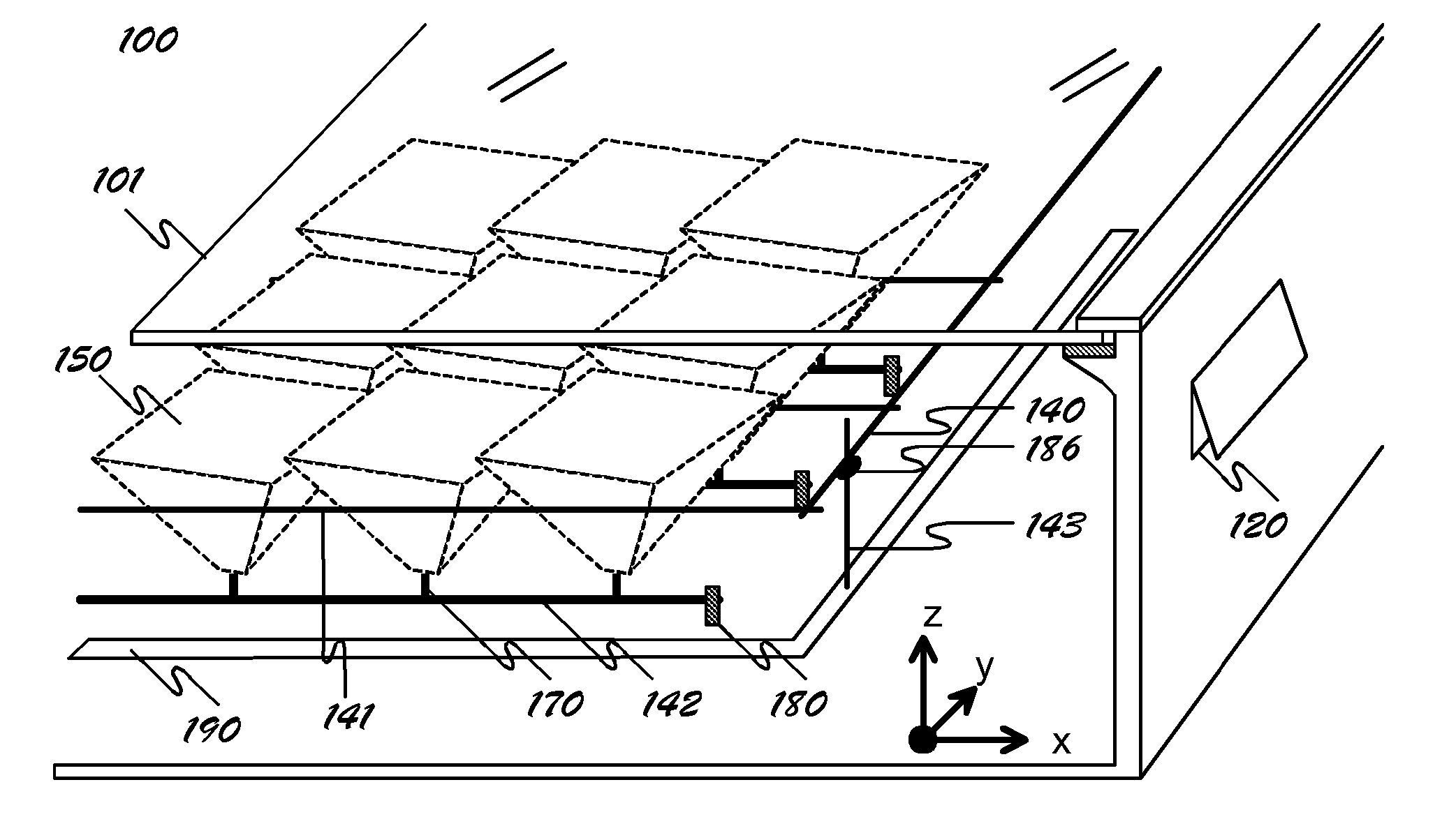
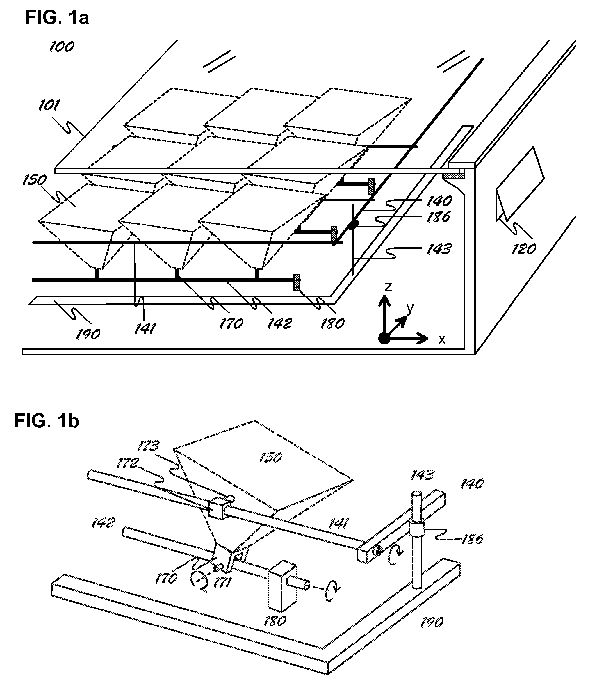
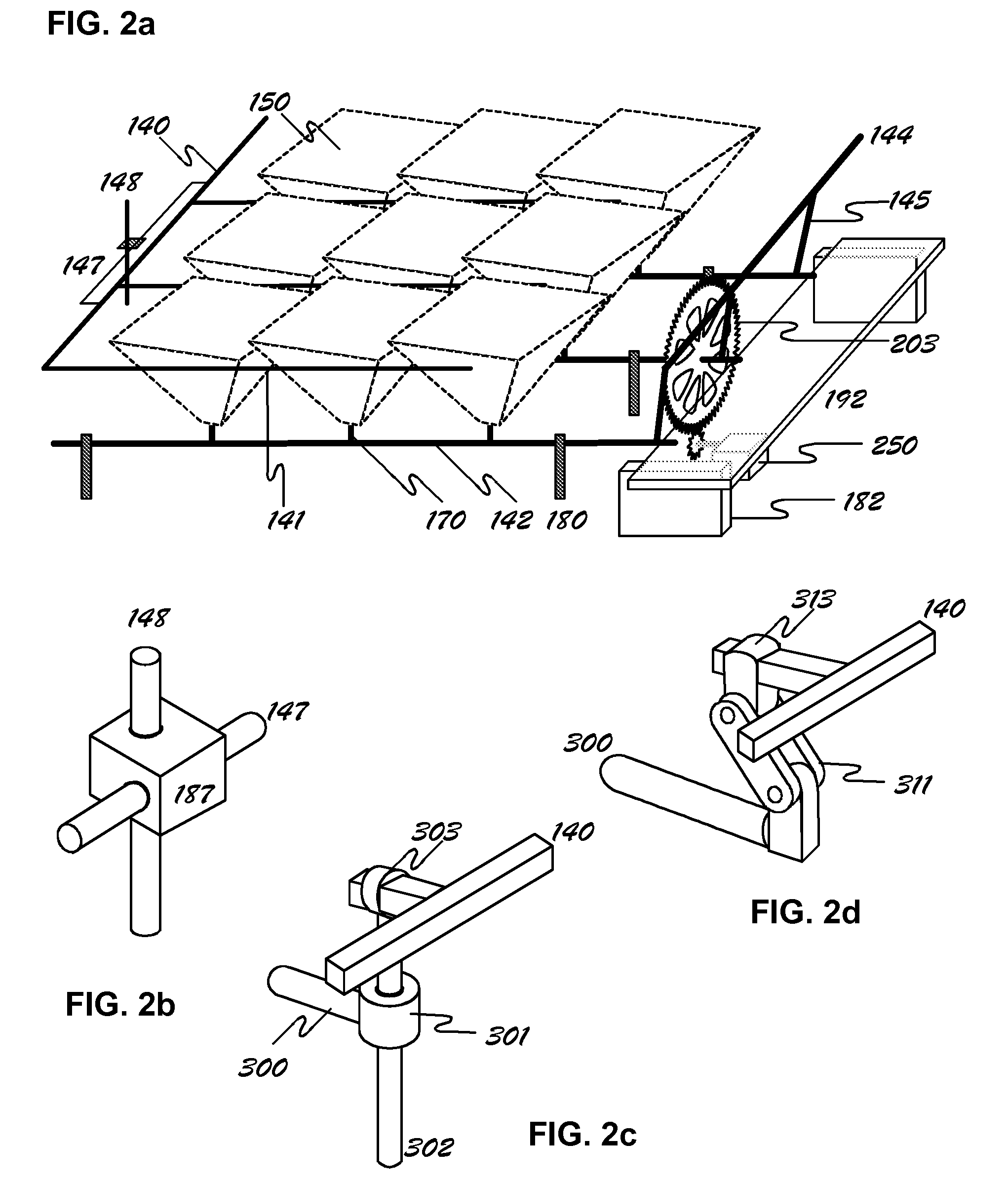
A radiant energy concentrating or collimating system comprising an enclosure that shields its contents from environmental effects while allowing radiant energy to transmit through its top window; a plurality of energy concentrating or collimating assemblies, each on its own pivot mechanism and each comprising a plurality of optics, a support structure and an energy conversion device that is mounted on a heat dissipating structure; a drive mechanism controlled by a microprocessor to rotate the said energy concentrating or collimating assemblies on two orthogonal axes in unison so the assemblies are oriented towards desired direction at any given time.

Description

FIELD OF THE INVENTION[0001]The present invention relates generally to radiant energy concentrating systems. More particularly, the invention relates to optical concentrators, collimators, and tracking devices that follow a radiant energy source to condense onto a collector such as a solar energy conversion device, or collimate and project a point source such as a light emitting diode to the target direction.BACKGROUND OF THE INVENTION[0002]The Photovoltaic (PV) industry is currently in rapid growth phase in the face of the unconstrained worldwide demand for energy and the deteriorating earth atmosphere caused by combustion emission gases. The supply of solar panels, dominated by polycrystalline silicon technology, is in severe shortage due to limited PV material supplies. Concentrator PV (CPV) systems have been recognized since 1950s for their significant reduction in the usage of precious PV materials by condensing sunlight to a cell that is up to 1000 times smaller than a non-con...

Claims


Application Information

Patent Timeline
Patent Type & Authority Patents(United States)
IPC IPC(8): H01L31/042F24J2/10F25D23/00F24S23/70F24S50/20
CPCF24J2/085F24J2/18F24J2/38F24J2/54F24J2/5424H01L31/052H02S20/23H02S40/44H01L31/0543H01L31/0547F24J2/12Y02B10/14F24J2002/5451F24J2002/5462F24J2002/5468F24J2002/5489Y02B10/12Y02B10/20Y02E10/42Y02E10/43Y02E10/47Y02E10/52Y02E10/60F24S23/31F24S23/71F24S23/79F24S30/40F24S30/455F24S50/20F24S2030/131F24S2030/134F24S2030/136F24S2030/17H02S20/32H02S40/425Y02B10/10Y02E10/40
Inventor LU, ZHENGHAO JASON
Owner INLAND MARINE IND
Learn More