Hole saw and slug remover

a technology of slug removal and hole saw, which is applied in the field of hole saws, can solve the problems of time-consuming and dangerous removal of slugs, waste of time and effort in removing slugs from the cavity of holes, and the tendency of hole saws to walk around

Active Publication Date: 2010-04-08
WERNER TRAVIS E
View PDF14 Cites 39 Cited by
  • Summary
  • Abstract
  • Description
  • Claims
  • Application Information

AI Technical Summary

Benefits of technology

[0012]A still further aspect of the invention involves a method of using the hole saw with slug remover described immediately above. The method includes the steps of applying the pilot drill of the hole saw to a piece of material to be cut; rotatably driving the pilot drill and hole saw via the rotatable shaft in the second direction, causing the ejection plunger deployment and retraction mechanism to retract the ejection plunger towards the hole saw housing, so that a slug is cut out of the piece of material; and rotatably driving the pilot drill and hole saw via the rotatable shaft in the first direction, causing the ejection plunger deployment and retraction mechanism to force the ejection plunger downward to eject the slug.
[0013]Other features and advantages of the present invention will become more readily apparent to those of ordinary skill in the art after reviewing the following detailed description and accompanying drawings.

Problems solved by technology

Otherwise, during the cutting of hard material, the hole saw has a tendency to walk around the work piece during the sawing of the hole.
However, its removal can be a time-consuming activity that may even be dangerous if a user fails to disconnect the drill equipment from its power source.
Therefore, time is needlessly spent removing the slug from the cavity of the hole saw.
Because the material characteristics of the slug often vary, the user may have difficulty removing the slug from the hole saw.

Method used


Image

  • Hole saw and slug remover
  • Hole saw and slug remover
  • Hole saw and slug remover

Examples


Embodiment Construction

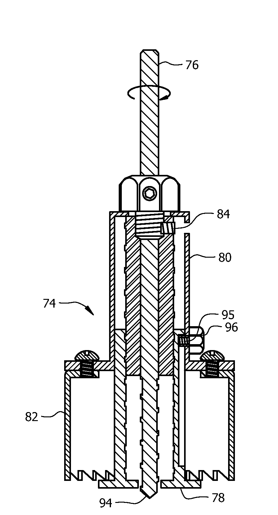
[0033]The embodiments of the present invention provide for the automatic removal of the slug lodged in the hole saw. By reversing the rotation of the drill, a ejection plunger protrudes from a portion of the hole saw, dislodging the slug and forcing it therefrom. After the slug is ejected from the hole saw via the ejection plunger, the hole saw can be used, without any further time delay, for additional cutting.

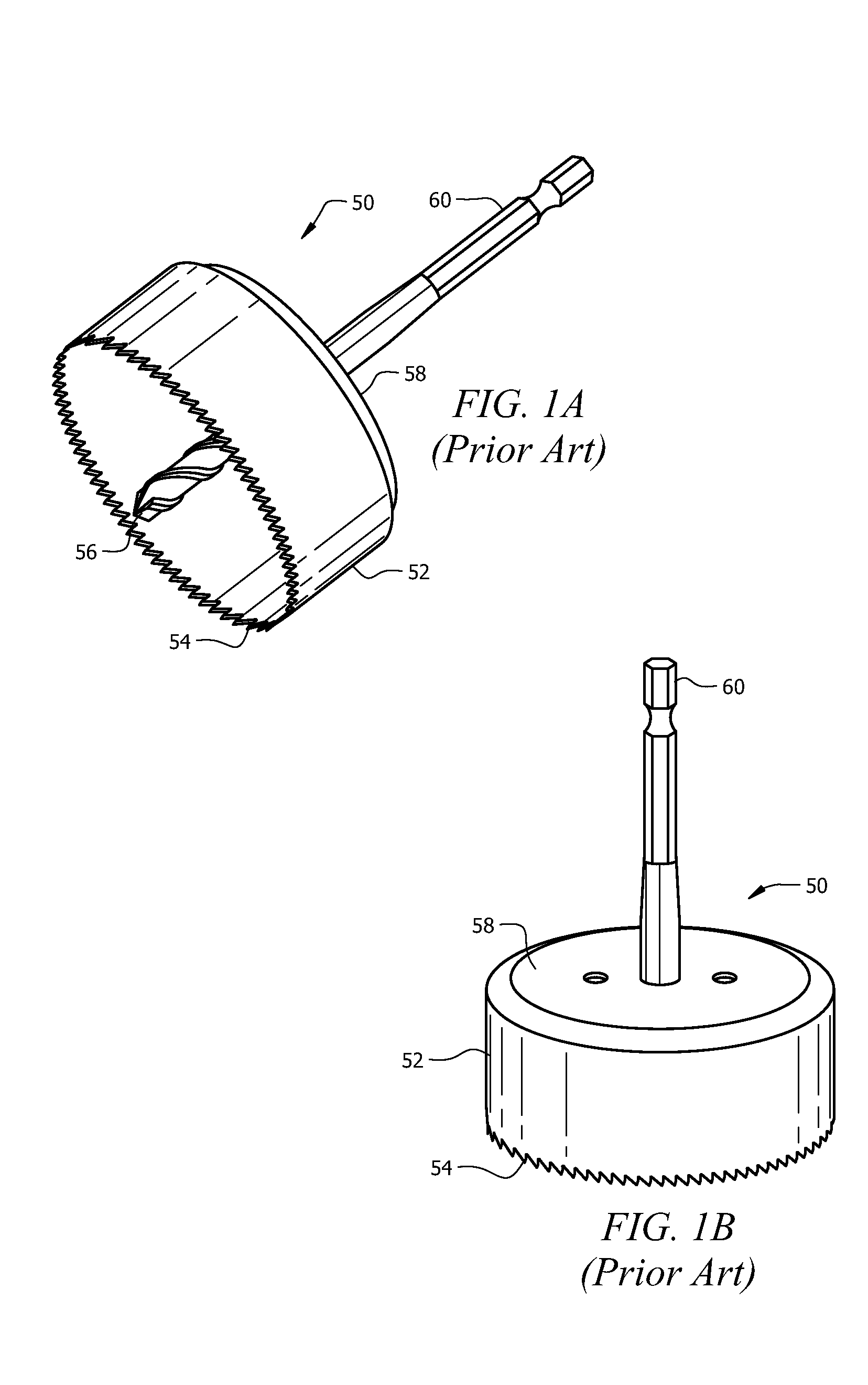
[0034]Turning to FIGS. 1A and 1B, a perspective view of a hole saw 50 comprising the prior art can be seen. As shown, a hole saw 50 of the prior art typically is comprised of a cylindrical body 52 having a closed end 58 and an open end 54, the open end 54 having a series of teeth for cutting into material. A shaft 60 is coupled to the closed end 58 of the cylindrical body 52. Additionally, a pilot drill 56 is coupled to the closed end 58 of the interior of the cylindrical body 52 and protrudes therefrom toward the open end 54, extending slightly beyond the teeth.

[0035]When th...


PUM

PropertyMeasurementUnit
angleaaaaaaaaaa
torqueaaaaaaaaaa
lengthaaaaaaaaaa

Abstract

A hole saw with slug remover including a top cylindrical housing; a bottom cylindrical housing attached to the top cylindrical housing, the bottom cylindrical housing having teeth for cutting; a pilot drill extending through the top cylindrical housing and bottom cylindrical housing; a drive screw rotatably affixed to the top cylindrical housing, the drive screw having a threaded exterior; and an ejection plunger engaging the threaded exterior of the drive screw wherein the ejection plunger is forced downward to eject a slug when the drive screw rotates counter-clockwise and is forced upward when the drive screw rotates clockwise.

Description

RELATED APPLICATION[0001]The present application claims the benefit of co-pending U.S. provisional patent application No. 61 / 103,364 filed Oct. 7, 2008, which is incorporated herein by reference in its entirety.BACKGROUND[0002]1. Field of the invention[0003]The present invention relates, in general, to hole saws, and, in particular, to hole saws with slug removers.[0004]2. Related Art[0005]Hole saws have been used for many years for the purpose of producing circular apertures at prescribed locations on both planar and curved surfaces. A typical hole saw comprises a cylindrical saw that forms a heavy base end with a threaded axially aligned hole in the bore. The hole saw is usually mounted to a coaxially positioned pilot drill by a mandrel fastened within a hole formed in the top of the hole saw.[0006]The pilot drill extends past the cutting edge of the hole saw so that a pilot hole is cut into the material first before the hole saw begins to remove a circular plug of material from t...

Claims


Application Information

Patent Timeline
Patent Type & Authority Applications(United States)
IPC IPC(8): B23B35/00B23B47/00B23B51/04
CPCB23B51/0453Y10T408/03Y10T408/51Y10T408/895
Inventor WERNER, TRAVIS E.
Owner WERNER TRAVIS E
Why Eureka
Try Eureka