
Fuel nozzle assembly

a technology of fuel nozzles and assembly parts, which is applied in the direction of combustion types, lighting and heating apparatuses, instruments, etc., can solve the problems of destroying the fuel nozzle, difficult to determine whether or not a flashback has occurred, and more difficult to keep the flame out of the fuel nozzl

Inactive Publication Date: 2010-04-15
GENERAL ELECTRIC CO
View PDF31 Cites 24 Cited by
  • Summary
  • Abstract
  • Description
  • Claims
  • Application Information

AI Technical Summary

Problems solved by technology

When the fuel used is hydrogen, it is much more difficult to keep the flame out of the fuel nozzle.
If the flame “flashes back” into the pre-mixer for any length of time it will destroy the fuel nozzle, since the flame temperature is almost always higher than the melting temperatures of the nozzle parts.
Flashback damage has historically been detected using NOx emission and exhaust temperature spreads as indicators.
The unpredictable behavior of exhaust temperature spreads, coupled with the emissions data scatter, has made it difficult to determine whether or not a flashback has occurred using NOx and exhaust spread indicators.
Therefore, methods which rely on changes in NOx and exhaust profile over sequential instants of time to determine if a flashback has occurred are ineffective.
This does not help determine a flashback event at the instant it occurs.
As discussed above, the process of first sensing the flashback event is an unreliable or slow process.
If the flashback event is not corrected in a very short period of time, or if the flashback causes a flame holding event within the nozzle, the nozzle can be irreparably damaged or destroyed.
The cost of adding flashback sensing equipment, control equipment and control valves to each nozzle is expensive.
In addition it is not practical to implement a control system on many individual injectors, which it is expected will be required in order to consistently burn hydrogen rich fuels.

Method used


Image

  • Fuel nozzle assembly
  • Fuel nozzle assembly
  • Fuel nozzle assembly

Examples


Embodiment Construction

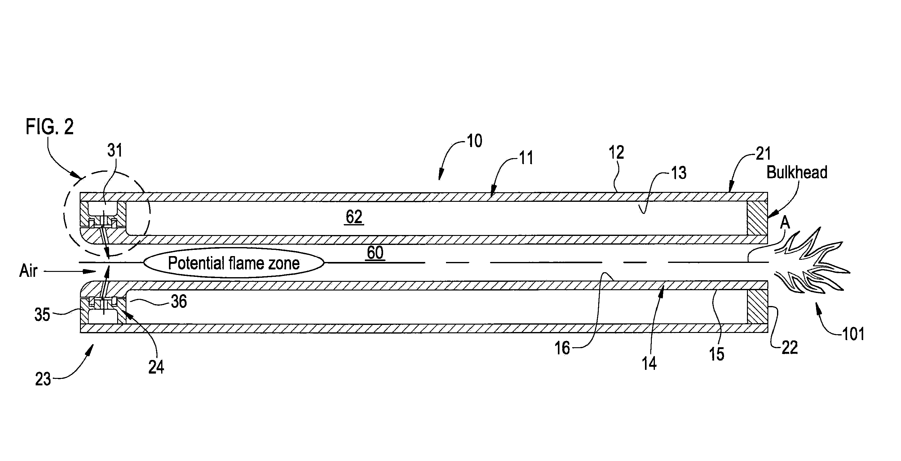
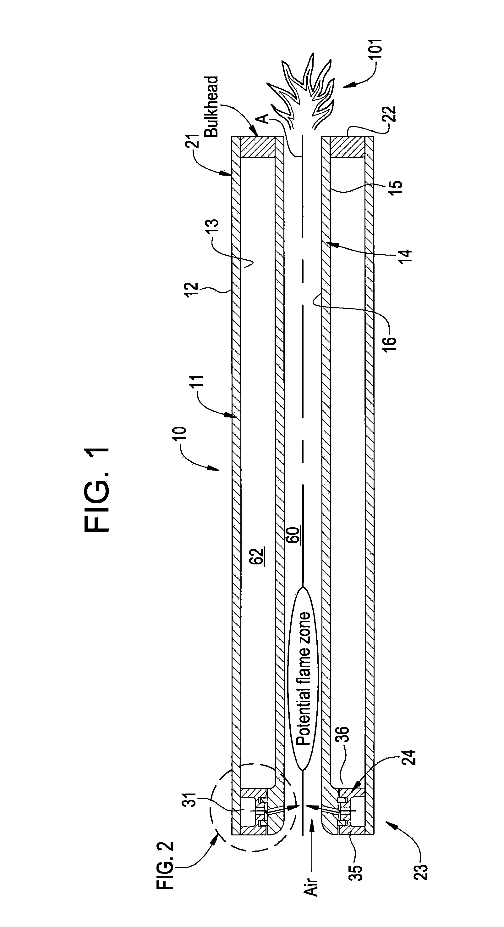
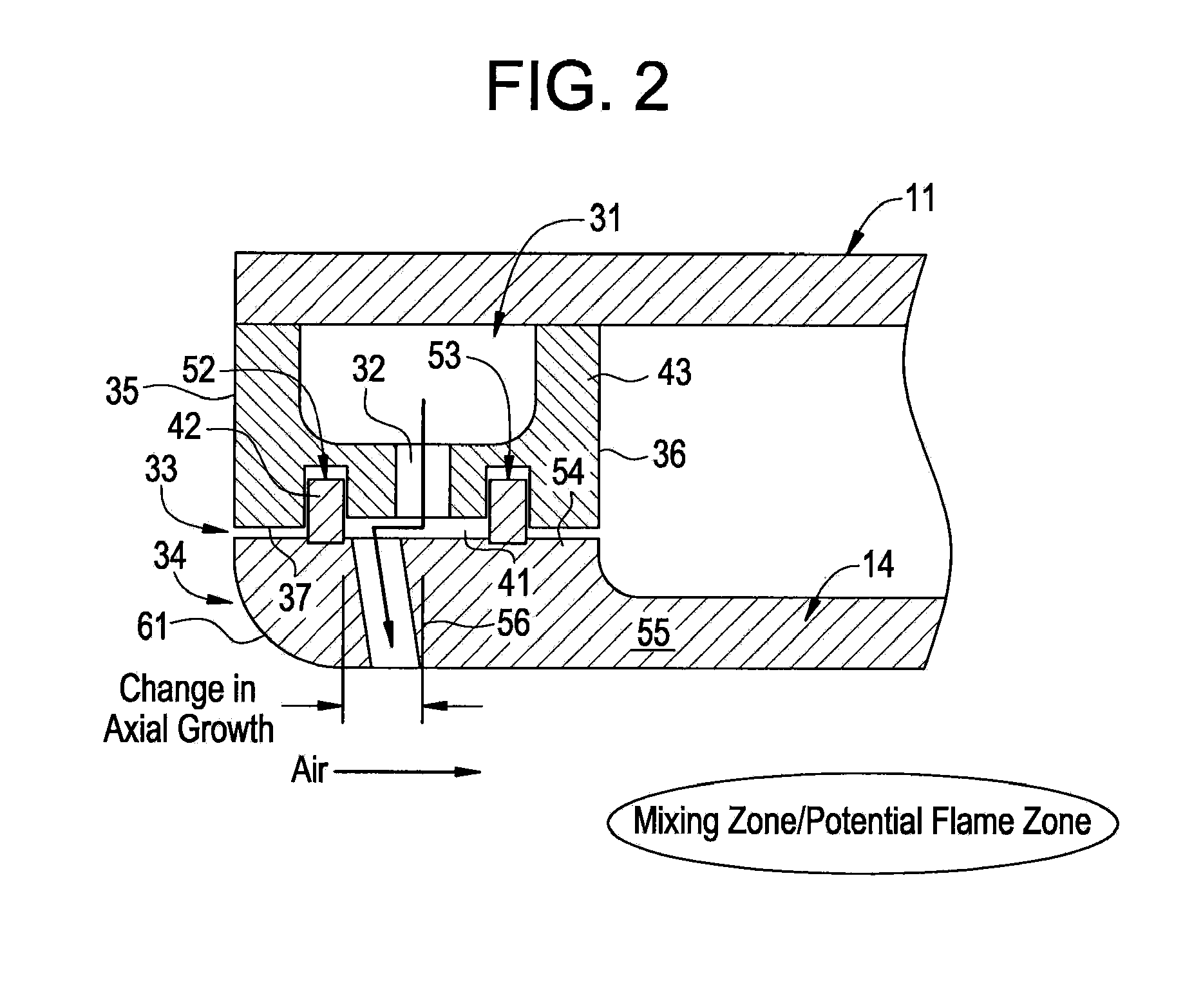
[0017]The present invention of a passive fuel extinction and nozzle is intended to shut off the fuel feed supplied to the fuel nozzle if a flame enters the nozzle. While one end of the nozzle body and nozzle tube is fixed, the opposite end is free to grow due to thermal expansion caused by the flame. The thermal growth causes one of the fuel injection orifice (or hole) to translate relative to the gas passage from a position generally in alignment that forms a fuel flow path therebetween. When the orifice and passage translate out of alignment, gas injection is blocked between the fuel plenum and the interior of the nozzle. As a result, the flame will go out.

[0018]Referring now to FIG. 1, where the invention will be described with reference to specific embodiments, without limiting same, a cross-section through a fuel nozzle 10 is shown. Fuel nozzle 10 includes an outer nozzle body 11 having an outer circumferential surface 12 and an inner circumferential surface 13. Fuel nozzle, 10...


PUM


Abstract

A fuel nozzle assembly is provided. The assembly includes an outer nozzle body having a first end and a second end and at least one inner nozzle tube having a first end and a second end. One of the nozzle body or nozzle tube includes a fuel plenum and a fuel passage extending therefrom, while the other of the nozzle body or nozzle tube includes a fuel injection hole slidably aligned with the fuel passage to form a fuel flow path therebetween at an interface between the body and the tube. The nozzle body and the nozzle tube are fixed against relative movement at the first ends of the nozzle body and nozzle tube, enabling the fuel flow path to close at the interface due to thermal growth after a flame enters the nozzle tube.

Description

FEDERAL RESEARCH STATEMENT[0001]This invention was made with the Government support under Contract No. DE-FC26-05NT42643, awarded by the Department of Energy. The Government has certain rights in this invention.BACKGROUND OF THE INVENTION[0002]The subject matter disclosed herein relates to fuel nozzles and more particularly to a nozzle which shuts off fuel feed if a flame enters the nozzle.[0003]The majority of pre-mix fuel nozzle builds are designed to pre-mix natural gas fuel. Today there is an emphasis on designing and building fuel nozzles that burn a hydrogen fuel. Hydrogen fuel is much more reactive, and thus, has a much higher flame speed. When designing fuel nozzles for pre-mixed combustion systems, the air and fuel are introduced upstream of where the combustion process takes place. Generally, fuel nozzles are designed to flow air through them at a rate that is faster than the flame can propagate upstream. When the fuel used is hydrogen, it is much more difficult to keep th...

Claims


Application Information

Patent Timeline
IPC IPC(8): F02M61/14
CPCF23D14/82
Inventor JOHNSON, THOMAS EDWARDZIMINSKY, WILLY STEVELACY, BENJAMIN PAULYORK, WILLIAM DAVIDSTEVENSON, CHRISTIAN XAVIER
Owner GENERAL ELECTRIC CO
Learn More