Fence post insulator

a technology of insulators and posts, applied in the field of insulators, can solve the problems of electrical shortening, electrical conductive, extremely tedious and time-consuming, etc., and achieve the effect of quick and easy mounting

Inactive Publication Date: 2010-04-15
CLIPPINGER BRAD ALAN
View PDF19 Cites 2 Cited by
  • Summary
  • Abstract
  • Description
  • Claims
  • Application Information

AI Technical Summary

Benefits of technology

This patent describes an easy way to install an insulator on an electric fence wire to create a resistant barrier between the wired fence and any nearby metal objects. It's made from a special type of plastic or rubber that helps prevent electrocution when someone touches it.

Problems solved by technology

The technical problem addressed in this patent is the difficulty and time consumption of installing traditional tubular insulators onto long lengths of electric fence wire and replacing them with new ones when needed without compromising the structure and effectiveness of the insulator. Therefore, there is a need for a simpler and easier way to install and replace fencepost insulators.

Method used


Image

  • Fence post insulator
  • Fence post insulator
  • Fence post insulator

Examples


Embodiment Construction

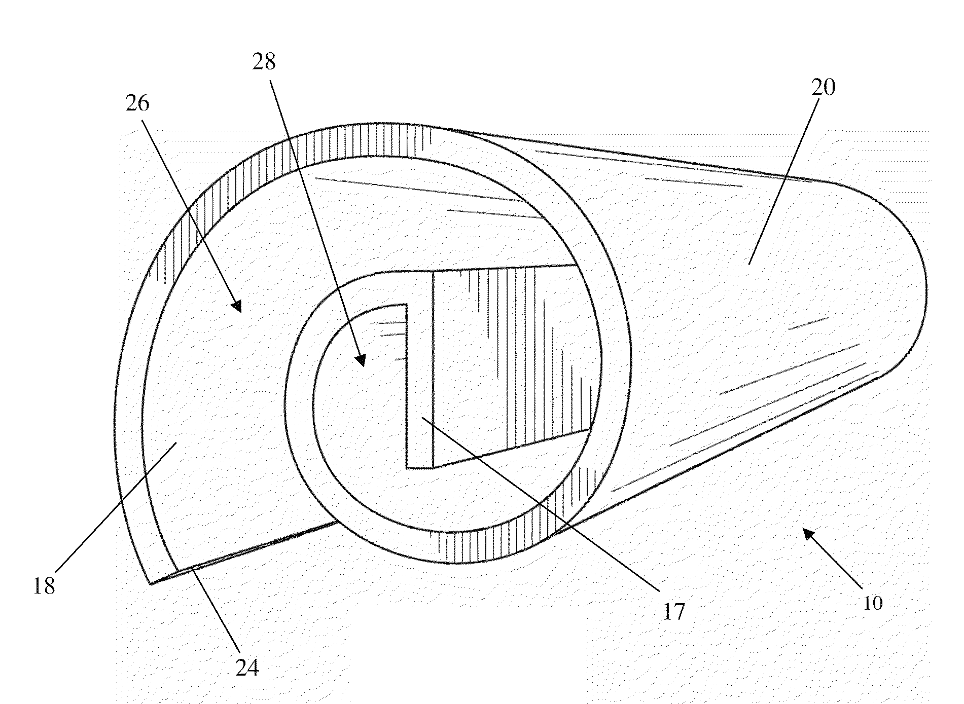
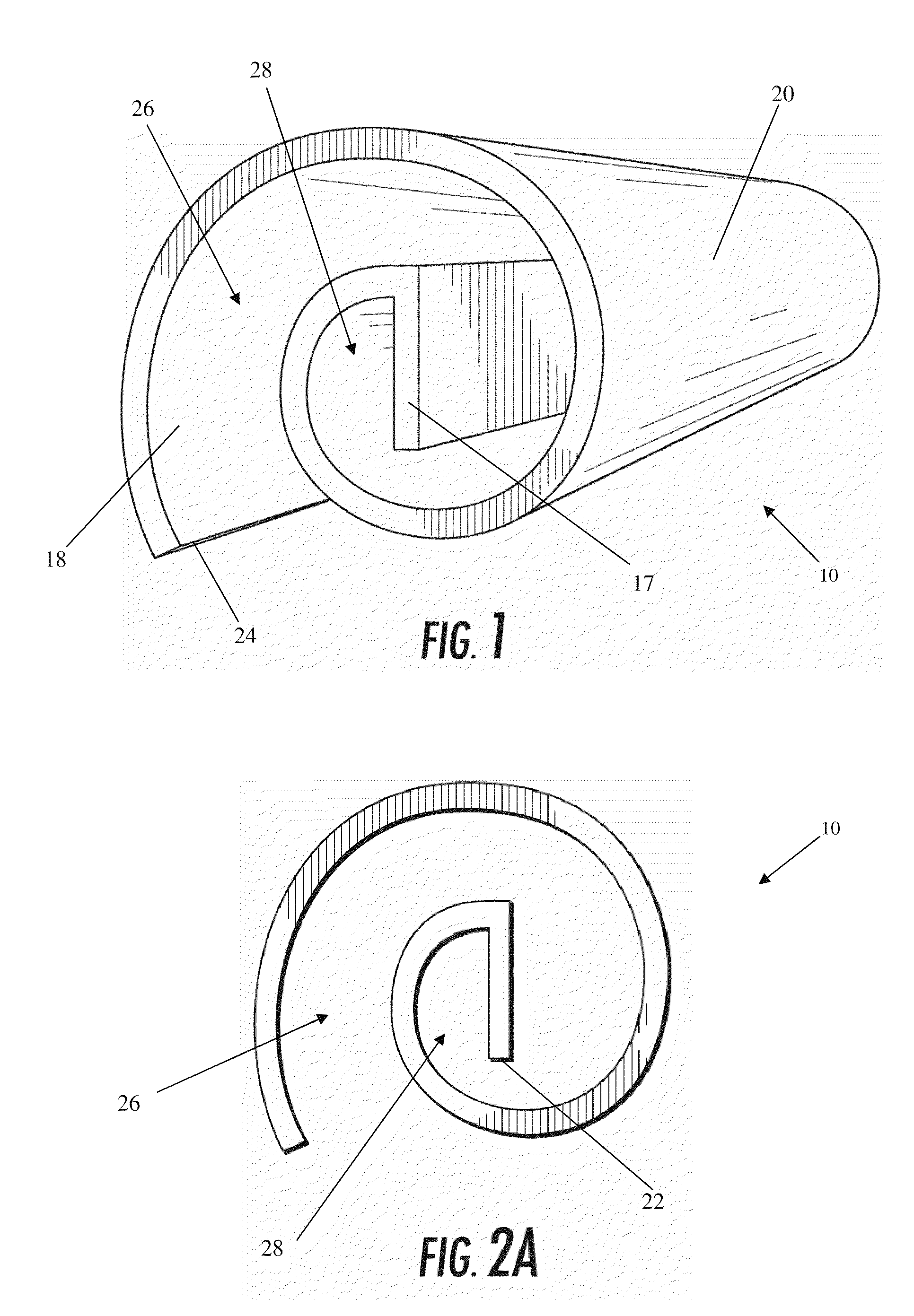
[0024]An improved electric fence insulator, indicated generally at 10, is shown in FIGS. 1, 2a, and 5. The insulator 10 can be quickly and easily mounted to a wire 12 of an electric fence for providing an electrically-resistive barrier between the electrified wire 12 and a conductive, non-conductive or semi-conductive fencepost 16.

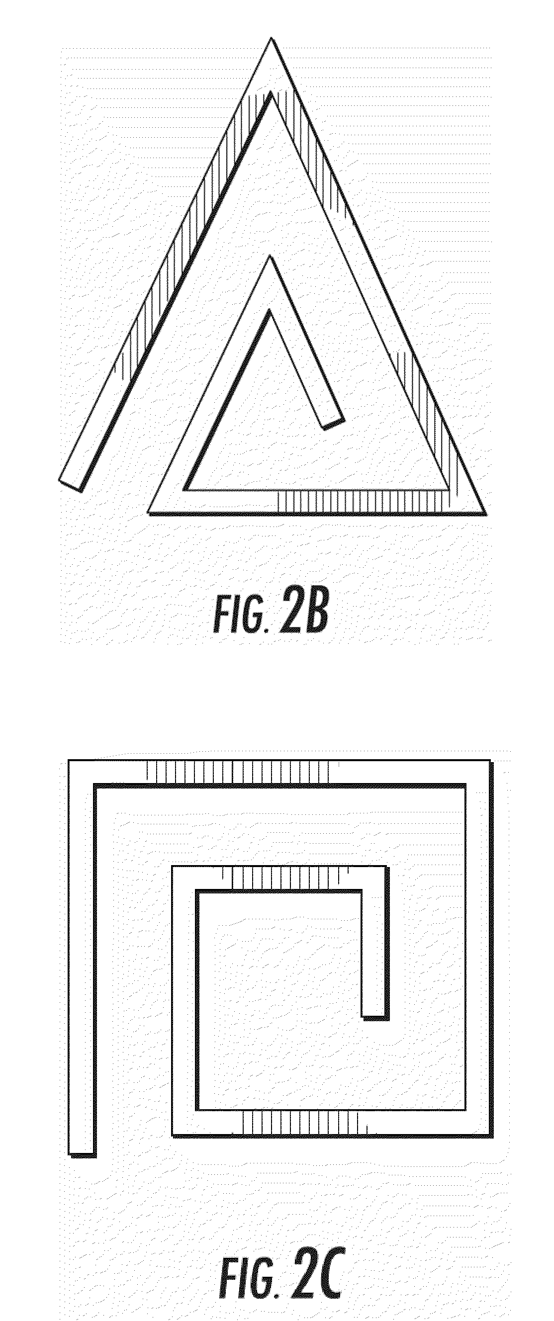
[0025]The insulator 10 is generally roll-shaped with a cross-section shaped like a loose circular spiral that terminates in an inwardly-extending, planar lip 17. The term “roll-shaped” is used herein to describe the configuration of the insulator 10 in the preferred embodiment shown in FIG. 1. “Roll-shaped” means the shape a relatively flexible sheet of material, such as stiff paper or plastic, takes when it is rolled from a plane into a tube, but without contact between overlapping layers of the material. Instead, a gap is formed between overlapping layers, as shown in FIGS. 1 and 2, and that gap is substantially the same dimension along the length of the...


PUM

PropertyMeasurementUnit
Lengthaaaaaaaaaa
Lengthaaaaaaaaaa
Thicknessaaaaaaaaaa

Abstract

A fencepost insulator that can be quickly and easily mounted on a wire of an electric fence for providing an electrically-resistive barrier between the electrified wire and a conductive fencepost. The insulator is a unitary, roll-shaped segment of electrically-resistive material with a loose spiral-shaped cross section. The insulator is installed by manually rolling the insulator onto a wire, thereby allowing the insulator to be conveniently installed at any location along the length of the wire.

Description


Claims


Application Information

Patent Timeline
Owner CLIPPINGER BRAD ALAN
Why Eureka
Try Eureka