Light touch sealant applicator device

a technology of applicator and sealant, which is applied in the direction of coating, other domestic articles, special surfaces, etc., can solve the problems of laborious application, laborious weather resistive barrier solution, and building requirements, and achieve the effect of easy cleaning and easy cleaning

Inactive Publication Date: 2017-03-23
ROHM & HAAS CO
View PDF2 Cites 1 Cited by
  • Summary
  • Abstract
  • Description
  • Claims
  • Application Information

AI Technical Summary

Benefits of technology

[0015]The chamber edge can comprise a flexible element adapted to strike, such as a squeegee or rubber wiper blade. The width, height and stiffness of the chamber edge can be chosen to suit the subst...

Problems solved by technology

While under construction, such buildings require a weather resistive barrier.
Several kinds of weather resistive barriers have been proposed, including flexible sheeting material and fluid materials, such as liquids and muds; however, each known weather resistive barrier solution is labor intensive.
In addition, such sheeting is must be fastened by hand to all exterior portions of the treated structure and has proven to be labor intensive to apply.
This means that the user must physically attach the sheeting to every portion of the exterior structu...

Method used


Image

  • Light touch sealant applicator device
  • Light touch sealant applicator device
  • Light touch sealant applicator device

Examples


example 1

[0072]A device in accordance with FIG. 3A has a circular “puck” shaped applicator head with a solid annular chamfered plastic chamber edge extending around the lower periphery of the chamber. The overall diameter of the plane that is parallel to the bottom most periphery of the chamber edge of the device and bounded by the outside of the chamber edge is 16.2 cm, The inner diameter of the chamber edge is 12.8 cm and the outside diameter of the chamber edge is 16.2 cm. Thus, the chamber edge width in contact with substrate is 1.7 cm.

[0073]The area of the total plane defined by the underside of the chamber and chamber edge is 3.14*(8.1)2 or 206 cm2. The surface area under the chamber and exposed to the substrate is 129 cm2. The surface area under the chamber edge is 77 cm2. Accordingly, the surface area open under the chamber is 63% of the total surface area of the plane parallel to the bottom most periphery of the edge of the device and open to the substrate during application of the ...

example 2

[0075]In an device as shown in FIG. 3B, with both round and square chambers worked to allow the device to ride on the foam being dispensed. A square chamber was 11.0 cm on a side and had a 1.0 cm wide edge fitted midway of its width with a row of bristles 0.2 cm wide and 0.3 mm tall, perpendicular to the chamber edge and also to the substrate when the device was used to apply acrylic foam. The row of bristles went completely around the perimeter of the chamber. The chamber underside tapered from the chamber edge up to the center opening 10, forming an approximately pyramidal open chamber (for square) or conical (for round) such that when the bristles on the lower periphery were in contact with a planar substrate, the apex of the pyramid and opening 10 were about 1.0 cm above the substrate.

[0076]The total surface area under the chamber and chamber edge was 100 cm2. The surface area of the plane parallel to the bottom most periphery of the chamber edge of the device and open to the su...


PUM

PropertyMeasurementUnit
Fractionaaaaaaaaaa
Glass transition temperatureaaaaaaaaaa
Volumeaaaaaaaaaa

Abstract

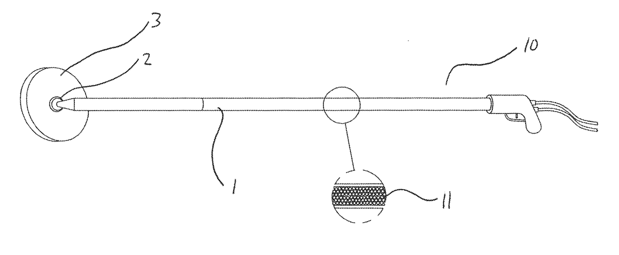
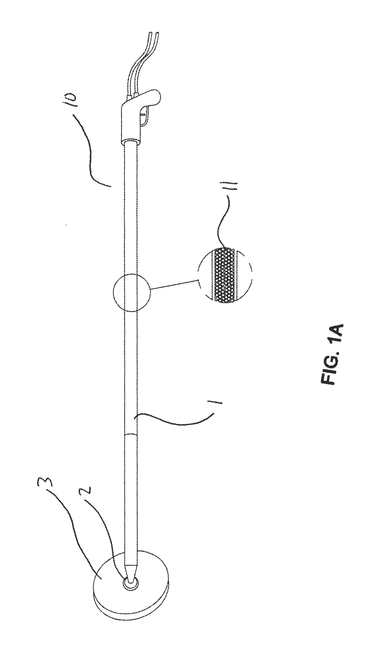
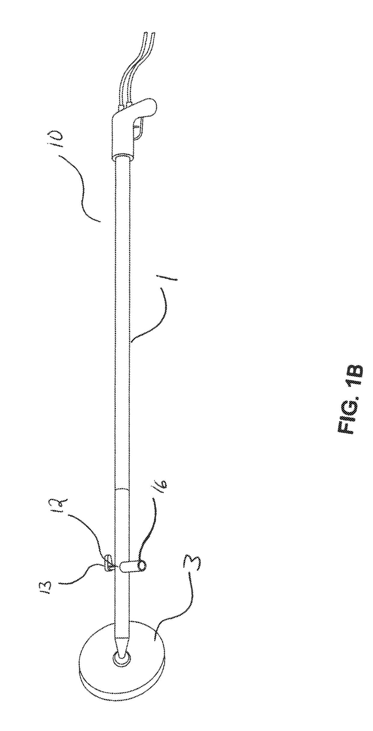
The present invention provides a device for applying a fluid sealant with a light touch, the device comprising a wand with a fluid sealant supply, either as part of the wand or as a separate supply tube, attached to the top of an applicator head via a universal joint, wherein the applicator head has a chamber on its underside which is sufficiently large to enable a constant supply of a fluid sealant to a substrate that is to be sealed, and the applicator head has a chamber edge disposed around its lower periphery adapted to strike the sealant flat. In addition, the present invention provides methods of using the devices to form a seal, e.g. a weather-resistive barrier on a sheathed building structure, by applying a flexible and compressible foam to gaps in the structure. The foam may comprise one or more aqueous polymer having a glass transition temperature of less than 25° C.

Description

[0001]The present invention relates to devices for applying a fluid sealant with little or no manual pressure or strain, and to methods for using the devices to provide a seal, such as a weather resistive barrier. More particularly, it relates to devices for applying foam sealants comprising a long handle or wand attached via a universal joint to the top side of an applicator head that has a chamber on its underside for continuously applying a sealant at any angle to gaps in a substrate, while moving the device in any desired direction.[0002]Building structures are commonly constructed with exterior wood, wood composite, cement or gypsum-based sheets, a.k.a. sheathing, that are overlaid with decorative facades or claddings (e.g., wood, aluminum or vinyl sidings or brick facades). While under construction, such buildings require a weather resistive barrier. Several kinds of weather resistive barriers have been proposed, including flexible sheeting material and fluid materials, such a...

Claims


Application Information

Patent Timeline
IPC IPC(8): E04F21/08B05B15/06B05C17/10B29C44/18B05D7/00B05D5/00B29C70/74B05B7/00B05D1/26
CPCE04F21/08B05B7/0018B05B15/067B05B15/061B05C17/10B05D1/26B29L2031/10B05D5/00B29C70/745B29C44/18B29K2007/00B29K2105/04B29K2995/0058B05D7/54B05C17/00516B05C17/00506B05B15/62B05B15/654
Inventor BOWE, MICHAEL DAMIANSZEWCZYK, JANAH C.VERBARO, DAVID A.
Owner ROHM & HAAS CO
Why Eureka
Try Eureka