High and medium voltage switch apparatus with two interrupters, having common means for actuating the movable contacts of the interrupters

a high or medium voltage switch and interrupter technology, which is applied in the direction of air-break switches, high-tension/heavy-dress switches, contact mechanisms, etc., can solve the problems of reducing the friction force between the spigot and the corresponding cam groove, and reducing the number of disadvantages of the switch apparatus disclosed in that documen

Inactive Publication Date: 2010-04-15
ALSTOM TECH LTD
View PDF4 Cites 15 Cited by
  • Summary
  • Abstract
  • Description
  • Claims
  • Application Information

AI Technical Summary

Benefits of technology

[0023]Because of this additional ratio, the radius of the disk cam can be reduced.
[0043]The movable contacts may advantageously be of hollow tubular form in order to improve the cooling of each said apparatus during a switching operation.

Problems solved by technology

The disadvantages of the switch apparatus of that document are numerous.
That kind of switch apparatus calls for a large amount of space.
The disadvantages of the switch apparatus disclosed in that document are numerous.
The structures of the switch apparatuses taught in the documents discussed above all have the disadvantage that they give rise to a reaction force on the rotary shaft when the movable contacts are in the closed position, that is to say when they are in mutual engagement with their corresponding stationary contacts.
In other words, undesirable loads are applied to the rotary shaft and to the actuator situated upstream that causes the shaft to rotate.

Method used


Image

  • High and medium voltage switch apparatus with two interrupters, having common means for actuating the movable contacts of the interrupters
  • High and medium voltage switch apparatus with two interrupters, having common means for actuating the movable contacts of the interrupters
  • High and medium voltage switch apparatus with two interrupters, having common means for actuating the movable contacts of the interrupters

Examples


Embodiment Construction

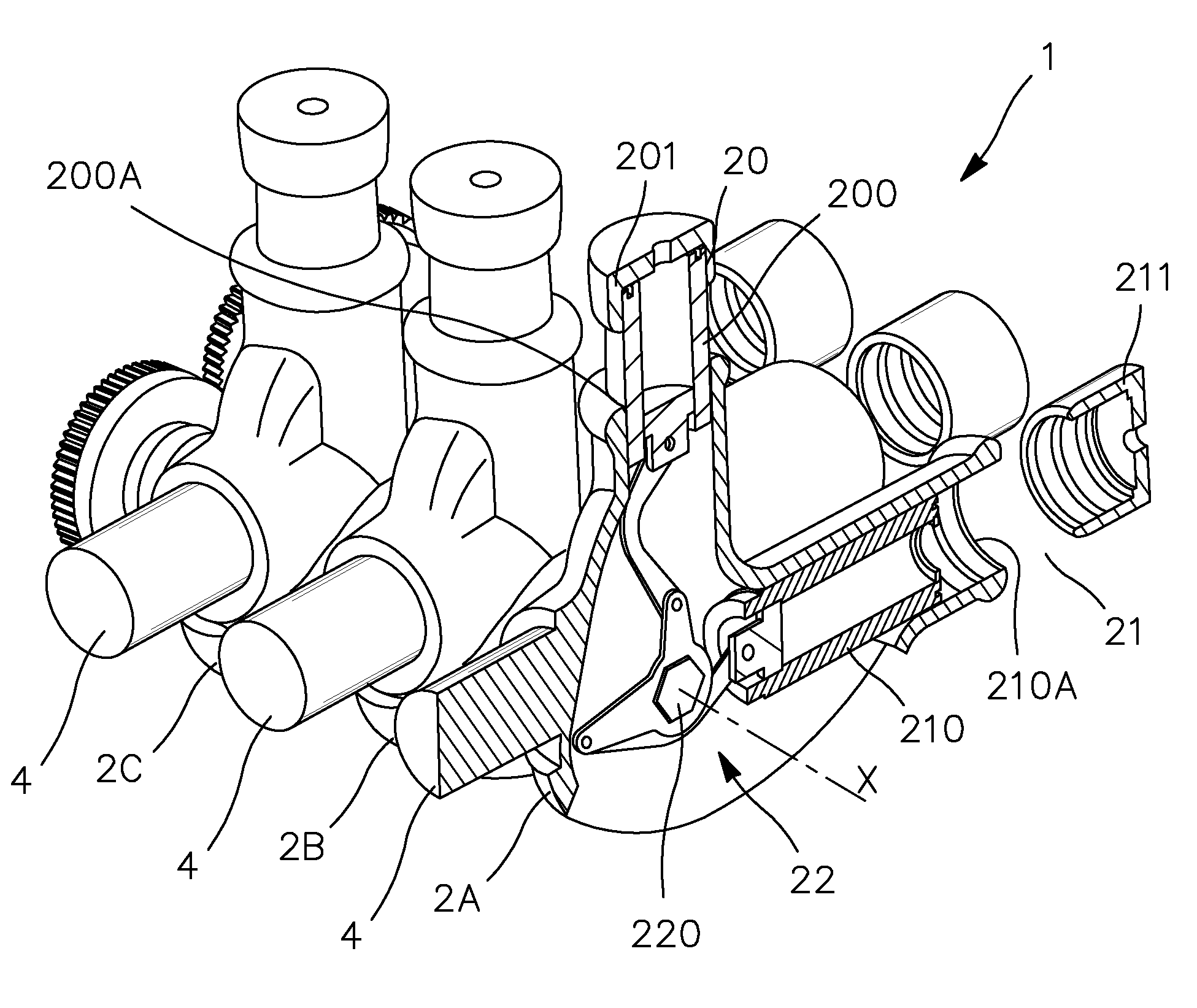
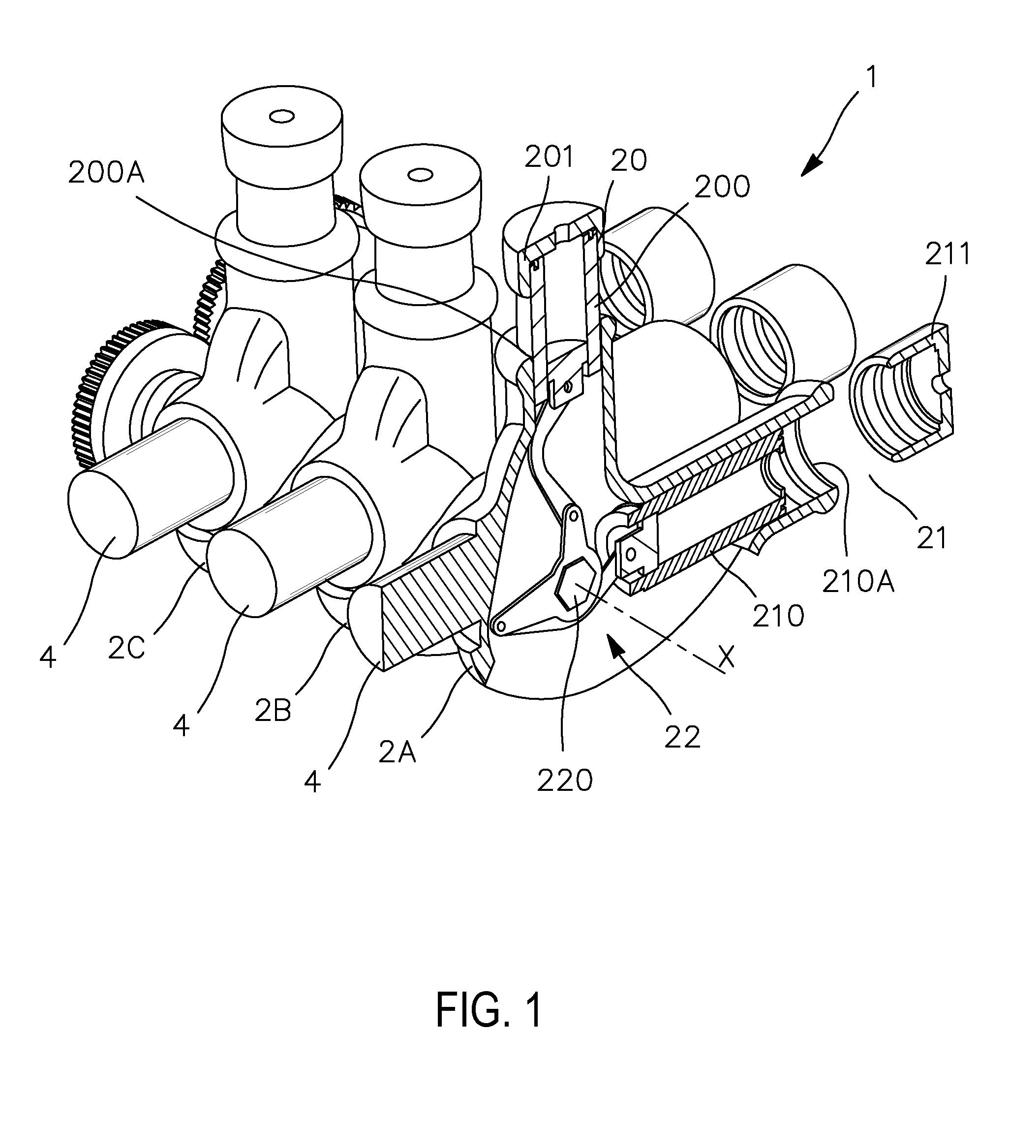
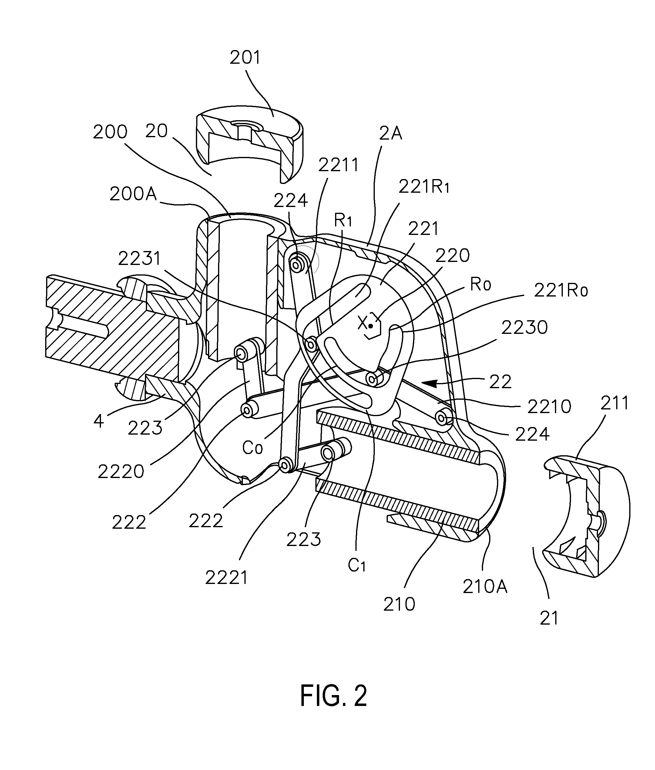
[0053]The figures described below show a switch apparatus 2A that conforms with the invention and carries out switching operations on a single pole. It goes without saying that the arrangement of a switch apparatus described below may be repeated for each pole in a multi-pole combination.

[0054]FIG. 1 shows part of a three-phase switch 1 having three identical casings 2A, 2B, 2C, in each of which a switch apparatus that conforms with the invention is lodged. These three identical phases are arranged inside a common metal casing (not shown), and are fastened to an insulating plate by the conductors 4 (see FIG. 2). In addition, an insulating bar 5, fastened to the three identical casings 2A, 2B, and 2C, is provided to give mechanical strengthening.

[0055]In the embodiments shown in FIGS. 1 to 5, the grounding disconnector 20 and the busbar disconnector 21 of one of the phases, 2A, are arranged substantially in a common plane and define an angle of 90° between them. It goes without sayin...


PUM


Abstract

This invention relates to the control of a switch apparatus having two interrupters, such as a busbar disconnector and a grounding disconnector.The invention provides:a rotary control shaft arranged away from, and at right angles to, the planes of straight line motion of the movable contacts;at least one disk cam fastened to the control shaft and having two distinct internal cam grooves; andtwo pairs of levers hinged to each other, with one of the levers of a given pair having one end hinged at a fixed point while its other end is hinged to the other lever of the same given pair, which is itself hinged to one of the movable contacts, a spigot being located between the two ends of each of the levers that has one end hinged at a fixed point, the spigot being engaged in one of the cam grooves so as to constitute a cam follower.The mechanism of the invention enables there to be an additional actuating ratio between the disk cam or cams and each associated movable contact.

Description

TECHNICAL FIELD[0001]This invention relates in general terms to the field of high or medium voltage switch apparatus having at least one interrupter.[0002]In particular, the invention is concerned with apparatus of this type in which at least one of the interrupters is a busbar disconnector and at least one of the interrupters is a grounding disconnector.[0003]More specifically, the invention relates to said type of switch apparatus in which each disconnector comprises a pair of contacts that consist of a stationary contact and a contact that is movable in straight line motion, for the purpose of separating from each other during a switching operation.[0004]The main application is medium or high voltage switchgear in which the busbar disconnector and grounding disconnector are disposed inside insulating casings, each of which is filled with a dielectric gas under protective atmosphere such as SF6.PRIOR ART[0005]The mechanical operations performed in this type of apparatus are common...

Claims


Application Information

Patent Timeline
Patent Type & Authority Applications(United States)
IPC IPC(8): H01H3/42
CPCH01H3/42H01H31/003H01H3/46
Inventor TREIER, LUKAS
Owner ALSTOM TECH LTD
Why Eureka
Try Eureka