
Texture Level Tracking, Feedback, and Clamping System for Graphics Processors

a technology of texture level and graphics processor, applied in the field of graphics processors, can solve the problems of reducing the visual affecting the performance of the model, and affecting the quality of the model,

Active Publication Date: 2010-04-15
ADVANCED MICRO DEVICES INC
View PDF8 Cites 19 Cited by
  • Summary
  • Abstract
  • Description
  • Claims
  • Application Information

AI Technical Summary

Problems solved by technology

The reduced visual quality of the model is often unnoticed because of the small effect on object appearance when distant or moving fast.
However, this method is generally difficult and inaccurate.
It also often results in the loading of mipmap levels and regions that are not required during rendering.

Method used


Image

  • Texture Level Tracking, Feedback, and Clamping System for Graphics Processors
  • Texture Level Tracking, Feedback, and Clamping System for Graphics Processors
  • Texture Level Tracking, Feedback, and Clamping System for Graphics Processors

Examples


Embodiment Construction

[0014]Embodiments of the invention as described herein provide a solution to the problems of conventional methods as stated above. In the following description, various examples are given for illustration, but none are intended to be limiting.

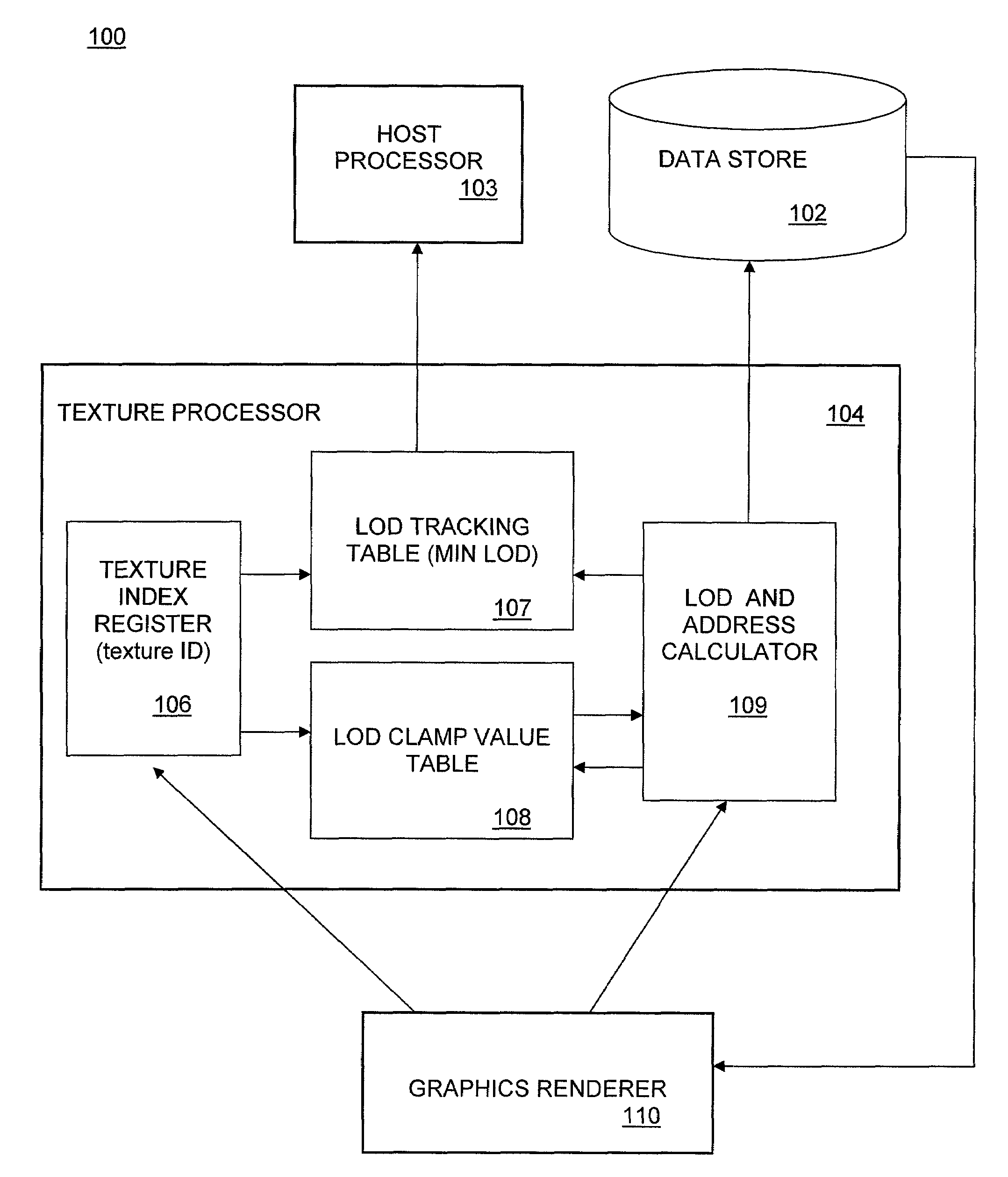
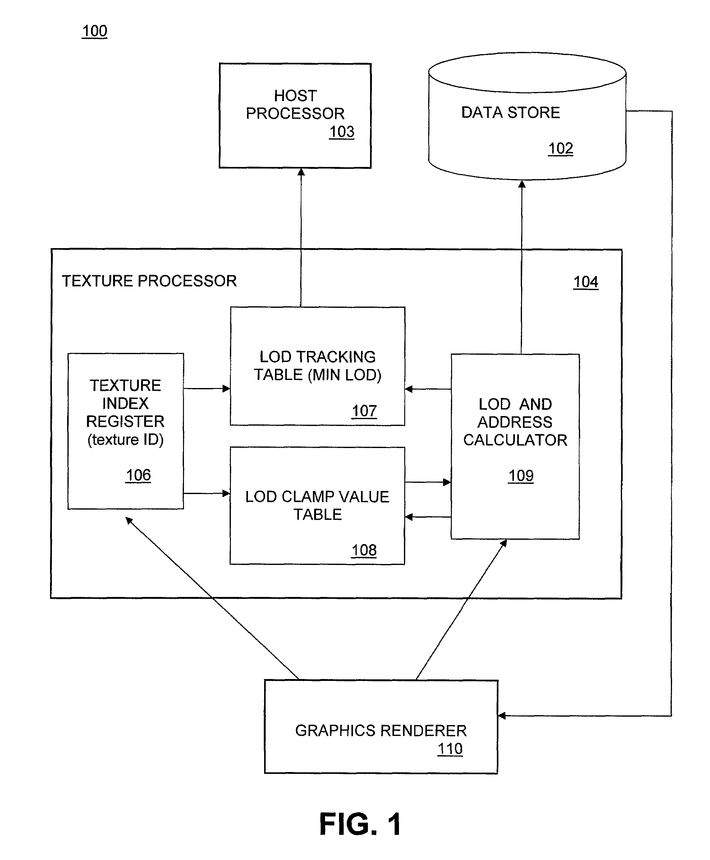
[0015]Embodiments include a texture mapping processor incorporating a dynamic level of detail tracking map for use in a graphics processing system. Texture mapping generally refers to a method for adding detail, surface texture, or color to a computer-generated graphic or 3D model, in which a texture map is mapped to the surface of a shape or polygon, such as the triangles that make up a wire-frame model. Texture coordinates are specified at each vertex of a given triangle, and these coordinates are interpolated through one or more algorithmic methods. In texture filtering, optimized collections of bitmap images, called “mipmaps” accompany a main texture to help increase rendering speed and reduce artifacts. Mipmap sizes generally depend on the...


PUM


Abstract

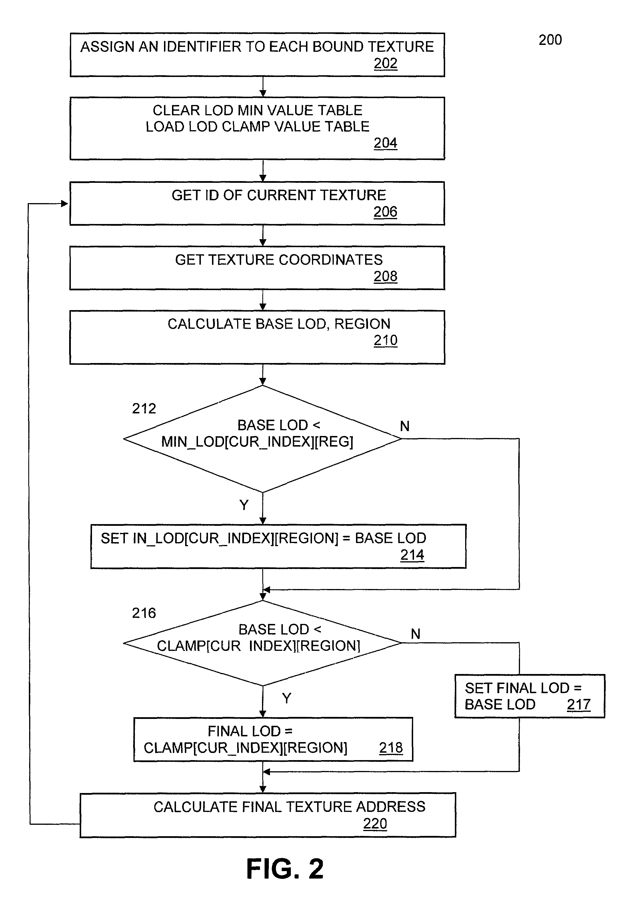
Embodiments include a texture mapping processor incorporating a dynamic level of detail map for use in a graphics processing system. Level of detail values are defined, with 0 being the finest and corresponding to the largest mipmap level. Each bound texture in a graphics object is assigned an identifier. This identifier is used as an index into a minimum-LOD value tracking table that is updated whenever a texel is fetched. A texture processing module controls when the tracking table is initialized and read back, and which identifiers are tracked. The minimum-LOD values in the tracking table are accompanied by a coarse region access mask to associate a minimum LOD value with a specific region of the image or object. A clamping table contains LOD clamp values for each region and a region code that specifies the coarseness of the LOD associated with each region of the texture.

Description

TECHNICAL FIELD[0001]The disclosed embodiments relate generally to graphics processors, and more specifically to methods and systems for efficiently loading texture maps in graphics processing systems.BACKGROUND OF THE DISCLOSURE[0002]Digital video systems typically employ one or more graphics processing units (GPU) to process video data. A GPU may be a dedicated graphics and video rendering device for computers, workstations, game consoles, and similar digital processing devices. A GPU is usually implemented as a co-processor component to the central processing unit (CPU) of the computer, and may be provided in the form of an add-in card (e.g., video card), co-processor, or as functionality that is integrated directly into the motherboard of the computer or into other devices (such as, for example, Northbridge devices and CPUs).[0003]One common function of graphics processor units is to process texture information. Texture mapping is a method for adding detail, surface texture, or ...

Claims


Application Information

Patent Timeline
Patent Type & Authority Applications(United States)
IPC IPC(8): G09G5/00
CPCG06T15/04
Inventor GROSSMAN, MARK S.FRISINGER, THOMASGESSEL, DANIEL M.
Owner ADVANCED MICRO DEVICES INC
Learn More