Optimal depth mapping

a depth mapping and depth mapping technology, applied in image analysis, instruments, computing, etc., can solve the problems of perceived depth being both compressed and distorted, and achieve the effect of optimizing stereoscopic images

Inactive Publication Date: 2010-04-15
REAID INC
View PDF30 Cites 74 Cited by
  • Summary
  • Abstract
  • Description
  • Claims
  • Application Information

AI Technical Summary

Problems solved by technology

This generally results in perceived depth being both compressed and distorted producing ‘cardboard cut-outs’ and flat ‘wall-paper’ backgrounds.

Method used


Image

  • Optimal depth mapping
  • Optimal depth mapping
  • Optimal depth mapping

Examples


Embodiment Construction

[0032]When two cameras of fixed separation capture a stereoscopic image pair from a real scene, the depth on a playback stereo display is non-linear. Uniformly-spaced objects (such as telegraph poles disappearing into the distance) appear to get closer together the further away they are. As used herein, the term “camera” refers to either a physical camera or a capture viewpoint in Computer Generated Imagery (CGI) virtual space. The present disclosure may relate to both a real-world capture environment and a CGI environment.

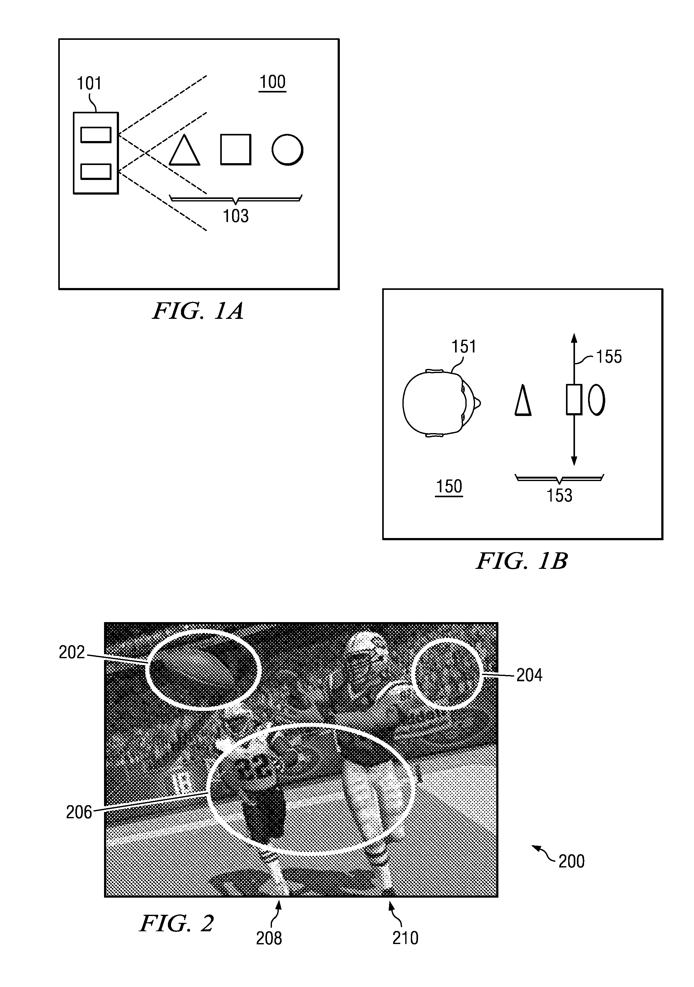
[0033]FIGS. 1A and 1B are schematic diagrams illustrating this depth distortion phenomenon. FIG. 1A illustrates the top view of a scene 100 with stereoscopic cameras 101 and substantially equally-spaced objects 103. FIG. 1B illustrates the top of the same scene 150 as visualized on a display. Viewer 151 faces a display with a display plane 155, and perceives the objects 153 at a non-uniform depth.

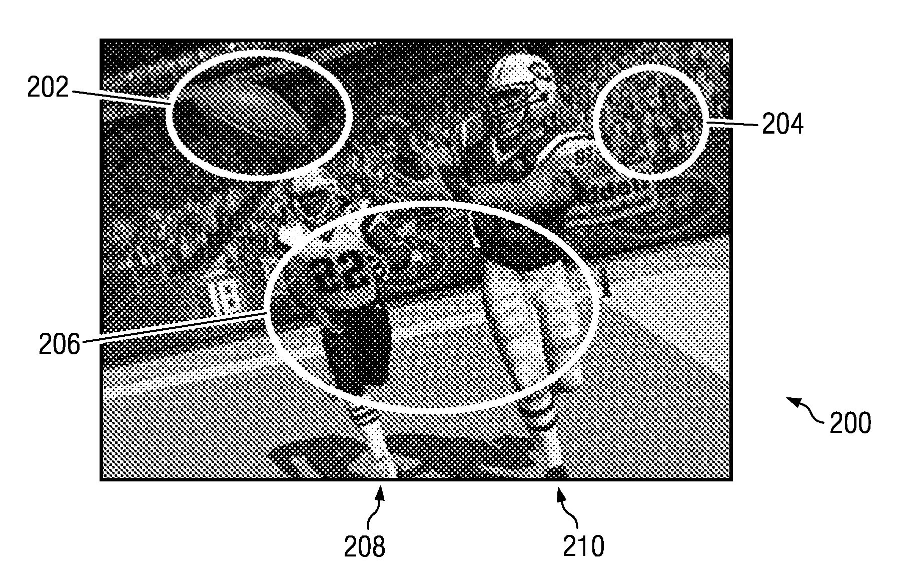
[0034]FIG. 2 is a schematic diagram illustrating a 3-D scene 200 and...


PUM


Abstract

A method and apparatus for providing optimal correction to depth mapping between captured and displayed stereoscopic content. The solution is derived in a continuous form that can be implemented through CGI scaling techniques compatible with image rendering techniques. Similar correction can be implemented with variable depth-dependent camera separation and disparity re-mapping. The latter is applicable to correcting existing stereoscopic content.

Description

CROSS-REFERENCE TO RELATED APPLICATIONS[0001]This application relates and claims priority to commonly-assigned U.S. Provisional Patent Application No. 61 / 102,493, filed Oct. 3, 2008, and entitled “Optimal Depth Mapping,” and to U.S. patent application Ser. No. 12 / 541,902, filed Aug. 14, 2009, and entitled “Stereoscopic depth mapping” (hereinafter “Stereoscopic depth mapping application”) both of which are incorporated herein by reference for all purposes. Pursuant to 37 CFR 1.7(b), this application is hereby filed on Monday, Oct. 5, 2008, which is the next succeeding business day following the one year anniversary of the filing of Prov. Pat. App. No. 61 / 102,493.TECHNICAL FIELD[0002]This disclosure relates generally to stereoscopic three-dimensional (3D) imagery and, more specifically, to depth mapping for stereoscopic images.BACKGROUND[0003]Stereoscopic capture and viewing has been commonplace since Charles Wheatstone invented the Stereoscope in 1833 as discussed in On Some Remarkab...

Claims


Application Information

Patent Timeline
Patent Type & Authority Applications(United States)
IPC IPC(8): H04N13/02H04N13/122
CPCG09G3/003G09G5/393G09G5/397H04N13/0275H04N13/0239G06T7/0075G06T15/20H04N13/0018G06T7/579G06T7/593H04N13/239H04N13/122H04N13/275H04N2013/0081H04N2013/0085
Inventor ROBINSON, MICHAEL G.
Owner REAID INC
Why Eureka
Try Eureka