Object position and orientation detection system

a technology applied in the field of object position and orientation detection system, can solve the problems of limited interactivity with such devices, high system cost,

Active Publication Date: 2010-04-15
CARL ZEISS IND MESSTECHN GMBH +1
View PDF20 Cites 181 Cited by
  • Summary
  • Abstract
  • Description
  • Claims
  • Application Information

AI Technical Summary

Benefits of technology

[0059]Preferably, a band pass filter is used to prevent imaging of electro...

Problems solved by technology

However, the level of interactivity with such devices is limited to little more than can be achieved with a stan...

Method used


Image

  • Object position and orientation detection system
  • Object position and orientation detection system
  • Object position and orientation detection system

Examples


Embodiment Construction

OF THE INVENTION

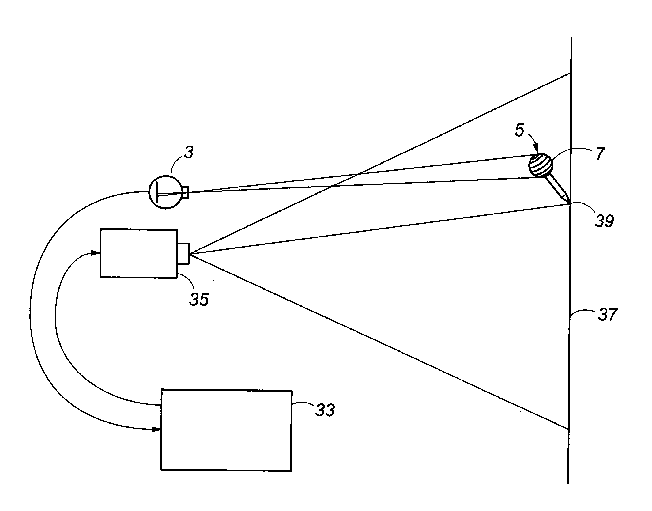
[0109]An embodiment illustrating the interface device 1 of the present invention is presented (with reference to FIGS. 3, 4, 5 and 8) which consists of a modified web camera 3 and a cylindrical pen 5 (the input device) with a 55 mm sphere 7 attached to the non-writing end. The sphere 7 has a ring 9 marked onto its surface along the equator, and other rings 11 parallel to the equator 9 repeating to the “north”13 and “south”15 poles of the ball 7.

[0110]Note that this embodiment describes using a modified web camera but it is of course envisaged that any camera could be employed for this purpose, for example a dedicated infrared camera could be used, or any camera tailor made to record images of the patterned marker in question.

[0111]The pen 5 contains a small battery 17 which supplies power to two LEDs 19 which in turn illuminate the stripe pattern on the ball 7. (Note that in practice this could be one or several LEDs). The LEDs 19 emit infrared light which means the ...


PUM


Abstract

An object position and orientation detection system and in particular one which is capable of describing observed movement in 3 dimensions. In one example, a spherical patterned marker with concentric rings is imaged using one or more digital cameras, and the resulting images are processed to determine the position and orientation of an object to which the patterned marker is attached. The method of optical tracking employed by the system allows motion to be determined in six degrees of freedom. In conjunction with a suitable display, such as a projector, an interactive white board or similar application can be realised.

Description

[0001]The present invention relates to an object position and orientation detection system and in particular one which is capable of determining observed movement in 3 dimensions.[0002]Interface devices which allow writing into a projected image using a touch sensitive surface spread across a board are known. However, the level of interactivity with such devices is limited to little more than can be achieved with a standard desktop mouse. Such systems are also expensive and require additional hardware purchases to bring them into effect.[0003]It is therefore an object of embodiments of the present invention to provide an object position and orientation detection system that can function without requiring additional expensive hardware.SUMMARY OF THE INVENTION[0004]In accordance with a first aspect of the invention there is provided an object position and orientation detection system comprising:[0005]an object, at least part of which comprises a patterned marker having a detectable pa...

Claims


Application Information

Patent Timeline
IPC IPC(8): G06K9/00H04N5/225G06V10/145
CPCG01B11/002G06F3/017G06F3/0325G06F3/0346G06K9/3216G06F3/0425G06F3/044G06K9/2036G06F3/03545G06F3/0304G06V10/145G06V10/245
Inventor VEESER, STEFANCUMMING, DAVID
Owner CARL ZEISS IND MESSTECHN GMBH
Why Eureka
Try Eureka