Heat dissipation member having variable heat dissipation paths and LED lighting flood lamp using the same

a technology of heat dissipation member and heat dissipation path, which is applied in the direction of lighting and heating apparatus, semiconductor devices for light sources, lighting support devices, etc., can solve the problems of affecting the design and application of led as light sources, affecting the lifespan or illumination, and unable to achieve waterproof effects, etc., to achieve the effect of preventing scald, enhancing design freedom, and improving heat dissipation

Inactive Publication Date: 2010-04-15
HYUNDAI TELECOMM
View PDF18 Cites 141 Cited by
  • Summary
  • Abstract
  • Description
  • Claims
  • Application Information

AI Technical Summary

Benefits of technology

[0027]According to the LED lighting flood lamp using a heat dissipation member having variable heat dissipation paths according to the present invention, since heat dissipation plates are covered by an upper cap so that the heat dissipation plates are not exposed to an outside, the dustproof and waterproof effects and prevention of a scald due to contact with high-temperature heat dissipation plates can be sought.
[0028]Also, by changing the heat dissipation paths formed by the arrangement

Problems solved by technology

The high-luminance LED emits superheat when it is turned on, and due to this superheat emission, there are difficulties in designing and applying the LED as a light source.
This exerts a bad effect on the lifespan or illumination of the LED lighting flood lamp vulnerable to

Method used


Image

  • Heat dissipation member having variable heat dissipation paths and LED lighting flood lamp using the same
  • Heat dissipation member having variable heat dissipation paths and LED lighting flood lamp using the same
  • Heat dissipation member having variable heat dissipation paths and LED lighting flood lamp using the same

Examples


first embodiment

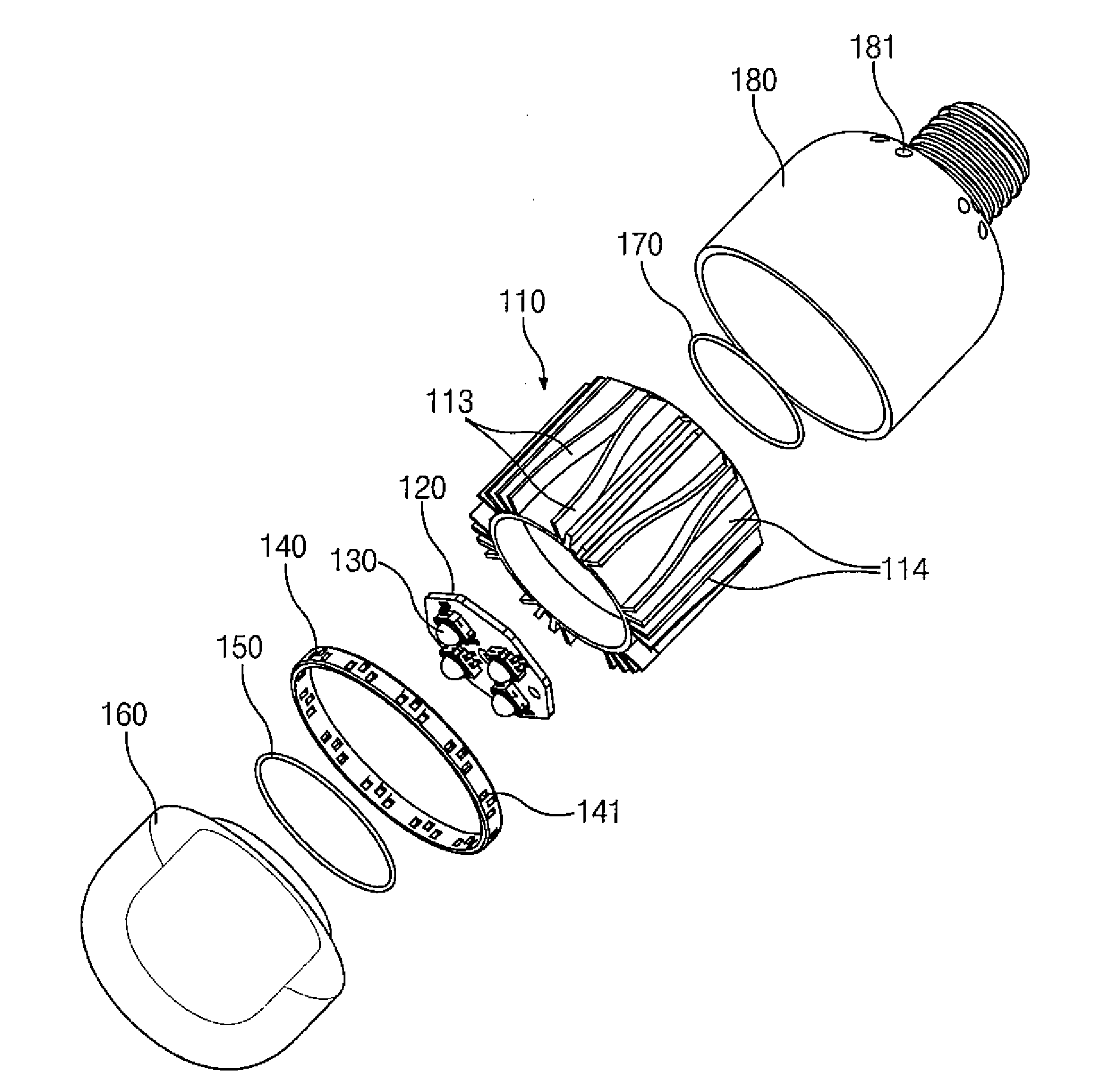
[0040]As illustrated, the LED lighting flood lamp 100 according to the present invention includes a plurality of LEDs 130; an LED mounting substrate 120 on which the LEDs 130 are mounted; a heat dissipation member 110 having a lower part to which the LED mounting substrate 120 is fixed, and provided with heat dissipation plates 113 and 114 formed on its circumference; an upper cap 180 fixed to outer surface of the heat dissipation member 110; a fixing ring member 140 fixed to the lower part of the heat dissipation member 110 to achieve inflow of outside air; and a lower lens 160 fixed to a lower part of the fixing ring member 140.

[0041]O-rings 150 and 170 are installed between an upper fixing part and a lower fixing part of the heat dissipation member 110 to improve the sealing performance. For example, the O-ring 170 is inserted between the fixing parts of the heat dissipation member 110 and the upper cap 180, and the O-ring 150 is inserted between the fixing parts of the heat diss...

second embodiment

[0059]On the other hand, FIG. 5 is a sectional view illustrating the structure of an LED lighting flood lamp using a heat dissipation member having variable heat dissipation paths according to the present invention.

[0060]The LED lighting flood lamp 100′ according to the second embodiment of the present invention may be provided by deleting the fixing ring member 140 from the LED lighting flood lamp according to the first embodiment of the present invention as described above. The lower end part of the upper cap 180 is further extended and penetration grooves 185 are formed on the circumference thereof so as to serve as the deleted fixing ring member 140.

[0061]In this case, the penetration grooves 185 are inclined grooves that can make the outside air smoothly flow to the heat dissipation paths.

[0062]In this embodiment of the present invention, the number of assembled components constituting the LED lighting flood lamp can be reduced, and the process and fixing work can be easily per...

third embodiment

[0063]FIGS. 6A to 6C are views illustrating an LED lighting flood lamp 300 using a heat dissipation member having variable heat dissipation paths according to the present invention. FIG. 6A is a perspective view of the LED lighting flood lamp, FIG. 6B is an exploded perspective view of the Led lighting flood lamp in FIG. 6A, and FIG. 6C is a sectional view taken along line C-C in FIG. 6A.

[0064]The LED lighting flood lamp 300 using a heat dissipation member having variable heat dissipation paths according to the third embodiment of the present invention includes LEDs 330; an LED mounting substrate 320 on which the LEDs 330 are mounted; a heat dissipation member 310 having a lower part to which the LED mounting substrate 320 is fixed, and having heat dissipation spaces 313 formed at predetermined intervals on the circumference of a cylindrical main body; an upper cap 380 fixed to the upper side of the heat dissipation member 310; a fixing ring member 340 fixed to the lower part of the...


PUM


Abstract

A heat dissipation member having variable heat dissipation paths and an LED lighting flood lamp using the same are provided, which can maximize heat dissipation effect by widening an air contact area and making air flow rapidly, seek a waterproof effect and prevention of a scald due to contact with a high-temperature heat dissipation plate, and prevent the reduction of heat dissipation efficiency caused by foreign substances by keeping wings of the heat dissipation plate not exposed to an outside. The LED lighting flood lamp using a heat dissipation member having variable heat dissipation paths includes LEDs, an LED mounting substrate on which the LEDs are mounted, a heat dissipation member having a lower part to which the LED mounting substrate is fixed and provided with the variable heat dissipation paths formed thereon, an upper cap fixed to outer surfaces of heat dissipation plates of the heat dissipation member; a fixing ring member fixed to the lower part of the heat dissipation member to achieve inflow of outside air, and a lower lens fixed to a lower part of the cap.

Description

CROSS-REFERENCE TO RELATED APPLICATION[0001]This application is based on and claims priority from Korean Patent Application No. 10-2008-100393, filed on Oct. 13, 2008 in the Korean Intellectual Property Office, the disclosure of which is incorporated herein in its entirety by reference.BACKGROUND OF THE INVENTION[0002]1. Field of the invention[0003]The present invention relates to a heat dissipation member having variable heat dissipation paths and an LED lighting flood lamp using the same, and more particularly, to a heat dissipation member having variable heat dissipation paths and an LED lighting flood lamp using the same, which can maximize heat dissipation effect by widening an air contact area and making air flow rapidly through variation of the size of the heat dissipation paths formed on the heat dissipation member, seek a waterproof effect through the use of O-rings and prevention of a scald due to contact with a high-temperature heat dissipation plate, and prevent the redu...

Claims


Application Information

Patent Timeline
IPC IPC(8): F21V29/00F21S4/00F21V1/00
CPCF21S48/328F21V29/004F21Y2101/02F21V29/83F21V3/02F21K9/13F21V29/74F21K9/135F21K9/23F21K9/232F21Y2115/10F21K9/235F21S45/47F21V17/10F21V31/005
Inventor SHIN, SUNG HO
Owner HYUNDAI TELECOMM
Why Eureka
Try Eureka