
Antenna Assemblies for Medical Applications

Active Publication Date: 2010-04-15
TYCO HEALTHCARE GRP LP
View PDF45 Cites 91 Cited by
  • Summary
  • Abstract
  • Description
  • Claims
  • Application Information

AI Technical Summary

Benefits of technology

[0012]Objects and features of the presently disclosed antenna assemblies will become readily apparent to those of ord

Problems solved by technology

During certain procedures, it can be difficult to assess the extent to which microwave energy will radiate into the surrounding tissue, making it difficult to determine the area or volume of the target tissue that will be ablated.

Method used


Image

  • Antenna Assemblies for Medical Applications
  • Antenna Assemblies for Medical Applications
  • Antenna Assemblies for Medical Applications

Examples


Embodiment Construction

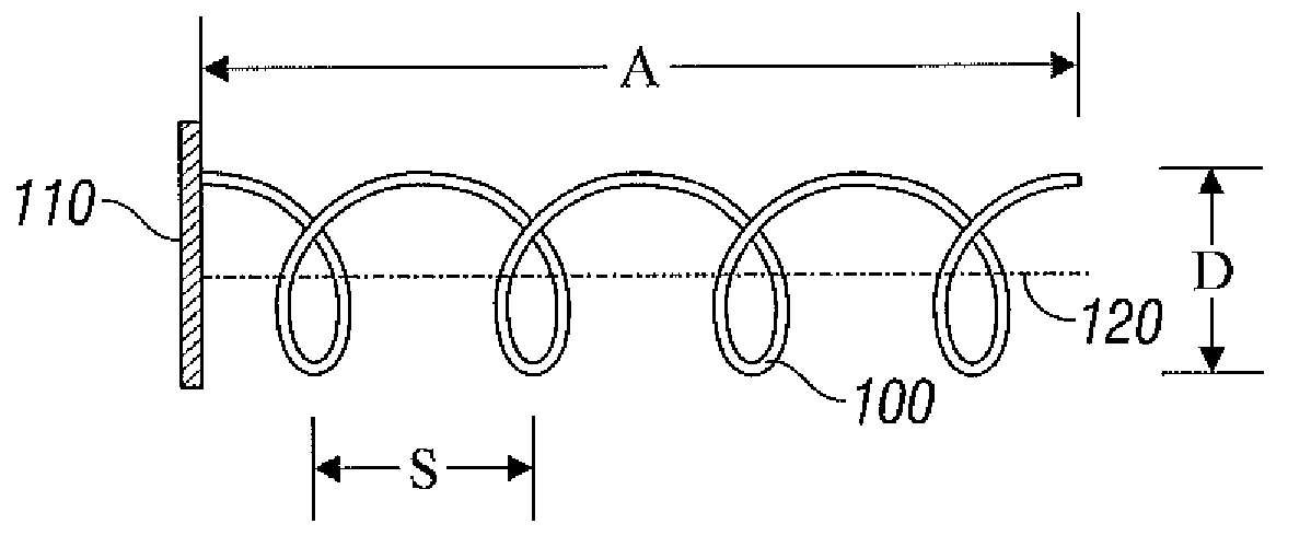
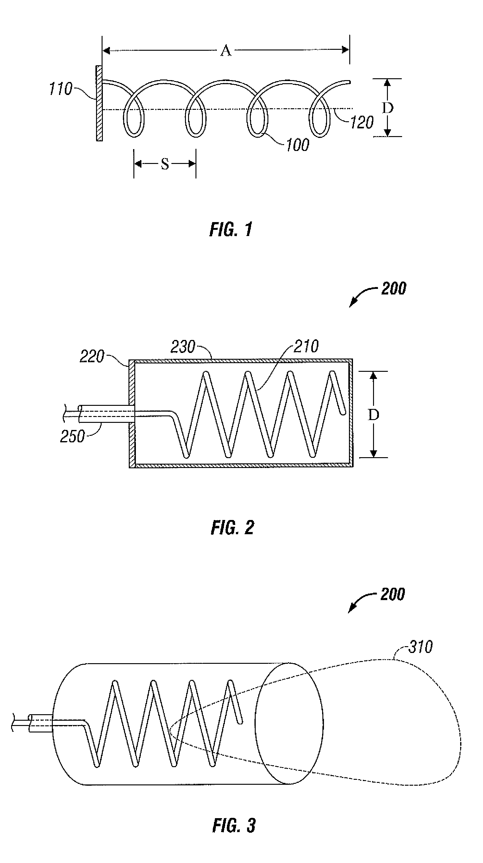
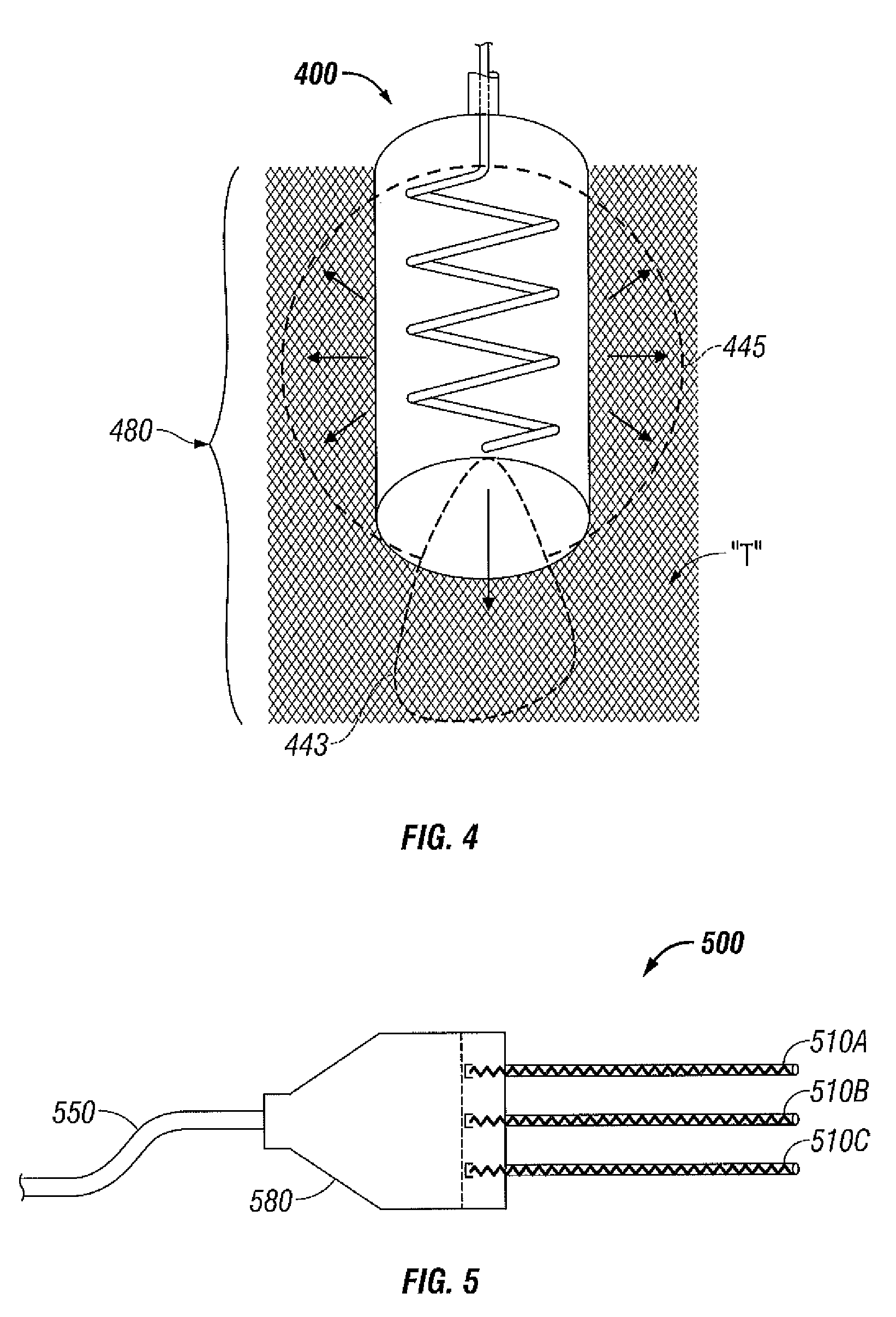
[0035]Hereinafter, embodiments of the presently disclosed antenna assemblies will be described with reference to the accompanying drawings. Like reference numerals may refer to similar or identical elements throughout the description of the figures.

[0036]As used herein, the phraseablation procedure” generally refers to any ablation procedure, such as microwave ablation or microwave ablation assisted resection. As used herein, the term “microwave” generally refers to electromagnetic waves in the frequency range of 300 megahertz (MHz) (3×10⁸ cycles / second) to 300 gigahertz (GHz) (3×10¹¹ cycles / second). As used herein, the phrasetransmission line” generally refers to any transmission medium that can be used for the propagation of signals from one point to another.

[0037]Various embodiments of the present disclosure provide electrosurgical devices for treating tissue and methods of directing electromagnetic radiation to a target volume of tissue. Embodiments may be implemented using ...


PUM


Abstract

A device for directing energy to a target volume of tissue includes a helical antenna assembly that includes a helical antenna radiating section having a helical antenna element. The helical antenna assembly is capable of operating in at least one of a first mode of operation for directing energy to a first portion of the target volume of tissue and a second mode of operation for directing energy to a second portion of the target volume of tissue.

Description

BACKGROUND[0001]1. Technical Field[0002]The present disclosure relates to antennas and, more particularly, to electrosurgical devices with antenna assemblies suitable for use in tissue ablation applications.[0003]2. Discussion of Related Art[0004]Treatment of certain diseases requires destruction of malignant tumors. Electromagnetic radiation can be used to heat and destroy tumor cells. Treatment may involve inserting ablation probes into tissues where cancerous tumors have been identified. Once the probes are positioned, electromagnetic energy is passed through the probes into surrounding tissue.[0005]In the treatment of diseases such as cancer, certain types of cancer cells have been found to denature at elevated temperatures that are slightly lower than temperatures normally injurious to healthy cells. Known treatment methods, such as hyperthermia therapy, use electromagnetic radiation to heat diseased cells to temperatures above 41° C. while maintaining adjacent healthy cells be...

Claims


Application Information

Patent Timeline
IPC IPC(8): A61B18/18
CPCA61B18/18A61N5/045A61B18/1815H01Q11/08
Inventor ROSSETTO, FRANCESCABRANNAN, JOSEPH D.PAULUS, JOSEPH A.
Owner TYCO HEALTHCARE GRP LP
Learn More