Vacuum Conveyance System

Active Publication Date: 2010-04-22
NAT INST OF INFORMATION & COMM TECH
View PDF8 Cites 3 Cited by
  • Summary
  • Abstract
  • Description
  • Claims
  • Application Information

AI Technical Summary

Benefits of technology

[0021]Magnets are generally heavy in weight. The ion pump of this mode, instead of using one cylindrical magnet, divides it into a plurality of cylindrical magnets and locates them at predetermined intervals. This can make the ion pump more lightweight and efficient magnetic fields can be obtained as well. Moreover, by using a plurality of small magnets easy to process instead of a large magnet hard to process, the difficulty in processing the shape or size of the pump casing is significantly improved.
[0022]The desirable mode of the first aspect of the present invention has a movement mechanism of magnets. The movement mechanism (14) moves the plurality of cylindrical magnets in the longitudinal direction of the casing (1). The movement mechanism (14) can change the region where magnetic fields concentrate. This can prevent the degradation of the system as well as improve the efficiency of the system. This configuration can be employed in any ion pump explained earlier. The movement mechanism may move magnets manually.
[0023]The desirable mode of the first aspect of the present invention relates to the cylindrical magnets which are removable from the casing (1). This ability to remove the cylindrical magnets improves productivity and makes maintenance easier.
[0024]The desirable mode of the first aspect of the present invention is configured so that adjacent surfaces of the plurality of cylindrical magnets have the sa

Problems solved by technology

Surfaces of semiconductors are subject to pollution by gas molecules.
For this reason, the magnetic fields are unidirectional, and the spaces in the ion pumps have not been able to be effectively utilized.
However, such ion pumps need to use many insulators such as ceramics in order to obtain insulation between electrodes.
For this reason, there is a problem that gases are emitted from ceramics etc., lowering a degree of vacuum.
There is

Method used


Image

  • Vacuum Conveyance System
  • Vacuum Conveyance System
  • Vacuum Conveyance System

Examples


embodiment 1

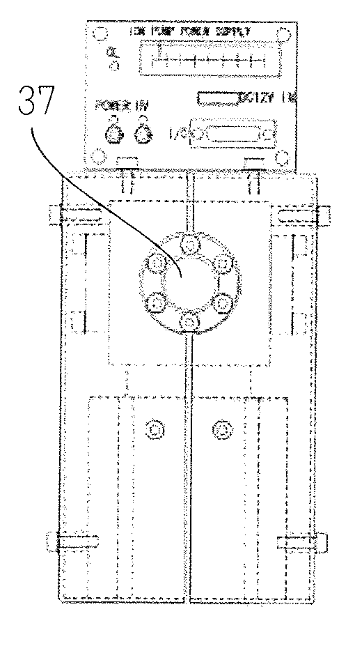
[0110]The prototypes of the ion pump and the vacuum carrying device concerning the present invention were manufactured. FIG. 15 is a photograph replacing a drawing showing a vacuum carrying device of the present invention.

[0111]In this ion pump, five ring-like permanent magnets are located at equal intervals in the circumference of the casing which concurrently serves as the negative electrode. In this vacuum carrying device, the frame was formed with aluminum having aluminum oxide film. Moreover, in another vacuum carrying device, the frame was formed with titanium having titanium oxide film. A 2.75″ gate valve having a 1.42″ routing port was used as a gate valve. An up-and-down clamp having a bellow was used as a sample lock. Batteries were used as a power supply. Moreover, a vacuum meter was placed for measuring the degree of vacuum in the sample room

[0112]This vacuum carrying device could locate samples with a maximum diameter of 35 mm. Moreover, high vacuum with internal pressu...


PUM


Abstract

It is an object of the present invention to provide a portable vacuum carrying system.
The above-mentioned problem is solved by a vacuum carrying system comprising an ion pump (6) comprising a casing (1), a positive electrode (2) provided in the casing (1), a negative electrode (3) fixed to the inner wall of the casing (1) and located on the circumference of the positive electrode (2), magnets (4) placed so as to surround the circumference of the negative electrode (3), and a connection part (5) for connecting the casing (1) to other device.

Description

TECHNICAL FIELD[0001]The present invention relates to a vacuum carrying system using an ion pump device etc. so miniaturized as to be carried by introducing three-dimensional magnetic fields.BACKGROUND ART[0002]With the development of nanotechnology and ultra-precision measuring technologies, ultrahigh vacuum technologies have been emphasized. Surfaces of semiconductors are subject to pollution by gas molecules. In contrast, by maintaining semiconductors in an ultrahigh vacuum below about 10−7 Pa, the surfaces of semiconductors can be kept clean. And pumps such as an ion pump are used to maintain an ultrahigh vacuum.[0003]As shown in FIGS. 4(A) and 4(B) in Japanese Patent Application Laid-Open No. H9-27294, for example, conventional ion pumps have arranged tabular permanent magnets so as to face each other in parallel across a cuboid container. For this reason, the magnetic fields are unidirectional, and the spaces in the ion pumps have not been able to be effectively utilized.[0004...

Claims


Application Information

Patent Timeline
IPC IPC(8): H01J41/12
CPCH01J41/12
Inventor TANAKA, SHUKICHI
Owner NAT INST OF INFORMATION & COMM TECH
Why Eureka
Try Eureka