Axial flux induction motor or generator

a technology of axial flux and induction motor, which is applied in the direction of mechanical energy handling, stator/rotor body manufacturing, and magnetic circuit shape/form/construction, etc., can solve the problems of reducing the overall size of the axial flux induction machine, and achieves smooth rotating magnetic field, high relative permeability, and high permeability.

Active Publication Date: 2020-10-01
TOREV CORP
View PDF0 Cites 0 Cited by
  • Summary
  • Abstract
  • Description
  • Claims
  • Application Information

AI Technical Summary

Benefits of technology

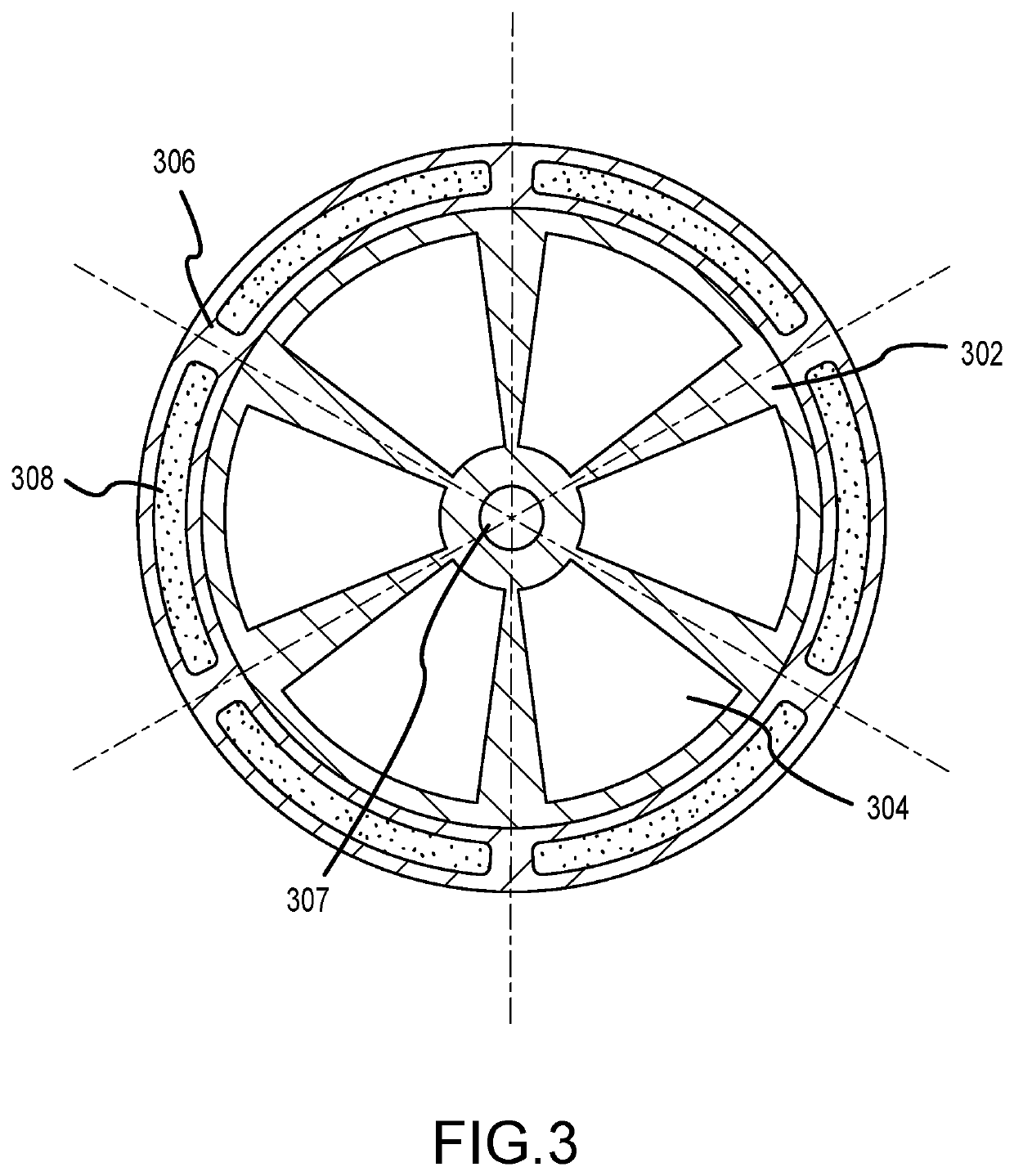
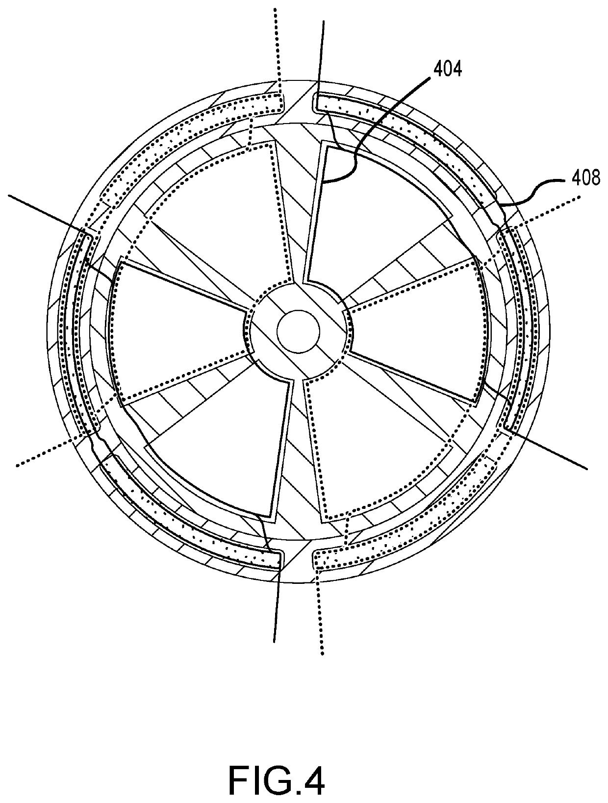
[0009]Some aspects of the current disclosure can be characterized as an axial flux induction machine comprised of a stator and rotor assembly. The stator core can be made from material capable of amplifying the magnetic field generated by the coils situated upon it. Such material is often referred to as high permeability material, due to having a high relative permeability. Two or more stator cores can be utilized in the herein-discussed embodiments. The number of rotors can be adjusted for the number of stator cores, such that the number of rotors can be one less than the number of stator cores. Where multiple generators or motors are combined, the number of rotors can be twice the number of stators. Other variations on the number of stators and rotors in also possible. The stator cores can be comprised of a disk with two rings of raised surfaces upon which a number of coils are situated. These surfaces may have a lip such as to secure the conductive coils in place (e.g., see FIG. 7), though this lip is not required. The coils may be separated by a degree determined by the number of phases utilized in operating the device. The coils can be arranged to overlap thereby providing a smoother rotating magnetic field and increase efficiency, possibly at the expense of cost, or to remain separate and result in cost savings while potentially sacrificing efficiency. The stator may also include an outer ring of raised portions upon which the coils can be wound. This outer ring may include a raised plateau below the coils as seen in FIG. 7. The inner and outer coils can be wound in opposing directions, and a single coil may be wound around a raised structure in the inner ring and a raised structure in the outer ring. The outer ring of raised portions may contact the outer ring of an opposing stator as shown in FIG. 9, while a small gap may be formed between opposing inner rings to leave room for the rotor. The rotor thickness may be minimized to reduce the air gap between inner rings on opposing stators. At the same time, this gap should be great enough to resist heat generated. The rotor can be secured to a shaft, and held in place by one or more bearings fitted in centrally located holes on both stators. The assembly may be held together by a supporting structure designed to prevent the stator plates from slipping apart while not under operation.
[0010]Other aspects of the current disclosure may include that the magnetic field of the stator structure can be designed to resemble that of a toroid. The toroid is an efficient electromagnetic

Problems solved by technology

Furthermore, the inclusion of the outer ring of coils can r

Method used


Image

  • Axial flux induction motor or generator
  • Axial flux induction motor or generator
  • Axial flux induction motor or generator

Examples


Embodiment Construction

[0033]The word “exemplary” is used herein to mean “serving as an example, instance, or illustration.” Any embodiment described herein as “exemplary” is not necessarily to be construed as preferred or advantageous over other embodiments.

[0034]Preliminary note: the flowcharts and block diagrams in the following Figures illustrate the architecture, functionality, and operation of possible implementations of systems, methods and computer program products according to various embodiments of the present invention. In this regard, some blocks in these flowcharts or block diagrams may represent a module, segment, or portion of code, which comprises one or more executable instructions for implementing the specified logical function(s). It should also be noted that, in some alternative implementations, the functions noted in the block may occur out of the order noted in the figures. For example, two blocks shown in succession may, in fact, be executed substantially concurrently, or the blocks...


PUM


Abstract

An axial flux induction machine comprises at least two stators and one rotor where the stators include an inner and outer ring of coils. The stator is comprised of two mirrored structures constructed such as to secure wire coils, amplify magnetic characteristics, and provide a structure upon which to secure a rotary shaft. The structures supporting the outer ring of coils can be in contact between the two stators and the outer ring can be spaced further from the rotary shaft than the inner ring of coils and also further from the rotary shaft than an outer edge of the rotor.

Description

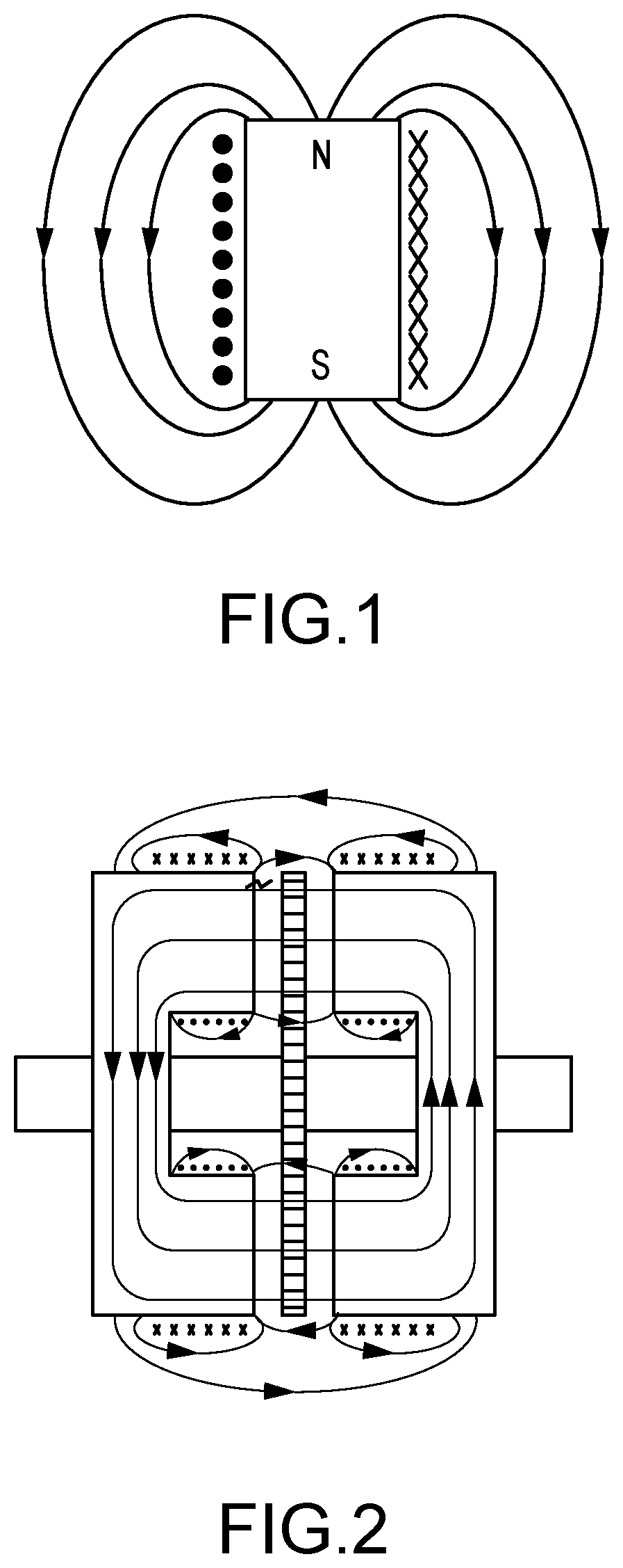
FIELD OF THE DISCLOSURE[0001]The present disclosure relates generally to an axial flux induction machine, specifically to an electric motor or generator that characterizes high performance through a more efficient magnetic circuit.DESCRIPTION OF RELATED ART[0002]The term “motor,” used here, references any type of electrical machine capable of converting electrical energy to mechanical energy through magnetic interactions producing rotary motion on a shaft.[0003]The term “generator,” used here, references any type of electrical machine capable of converting mechanical energy to electrical energy through magnetic interactions produced by the rotary motion of a shaft.[0004]An induction motor operates upon both Faraday's Law of Induction and Lenz's Law. A conductor experiencing a change in magnetic flux has a current induced therein. This induced current will produce a magnetic field, for instance, around the conductor as shown in FIG. 1. Within an induction motor, conductor coils are p...

Claims


Application Information

Patent Timeline
IPC IPC(8): H02K3/18H02K1/14H02K7/00H02K17/12H02K17/42H02K7/08H02K15/02H02K15/06
CPCH02K3/18H02K15/022H02K1/14H02K17/42H02K7/003H02K17/12H02K7/086H02K15/062H02K1/141H02K16/00H02K16/04
Inventor BROGAN, RODERICK JAMES
Owner TOREV CORP
Why Eureka
Try Eureka