
Turbine unit and assembly

Active Publication Date: 2010-04-29
BRADDELL
View PDF26 Cites 10 Cited by
  • Summary
  • Abstract
  • Description
  • Claims
  • Application Information

AI Technical Summary

Benefits of technology

[0014]Preferably the first turbine blade set and second turbine blade set are positioned such that when fluid flows through the first blade set, the first blade set rotates, and the second blade set is induced to rotate, as the second blade set rotates the fluid is pulled through the system to be pushed out the unit, minimizing the back flow pressure and energy loss. This is also the case in the reverse flow whereby the first turbine blade set acts to pull the fluid there towards. The act of pushing the fluid out of the passage also overcomes the pressure head which exists at the exit of the passage.
[0060]The turbine assembly may comprise a further nozzle wherein the turbine blade set is located between the two nozzles. The nozzle upstream from the turbine blade set may accelerate fluid towards the turbine blade set whilst the nozzle downstream from the turbine blade set slows the fluid down as well as reducing back flow pressure created by the turbine blade set.

Problems solved by technology

In relation to nuclear energy there are many significant disadvantages in the use of this fuel: waste disposal / storage, establishment costs and risk of accident, to name but a few.
In relation to renewable energy, such as wind, solar, and wave energy, the cost associated with the establishment of a sufficiently sized plant to harness the energy is, to date, a relatively expensive alternative.
Furthermore, the plant only generates energy from these sources if these sources are present.
As this is not always the case, the plant may lay idle, unable to produce any energy until the wind blows, the sun is present or the swell improves.
As a result, these sources are only used to supplement energy supplied through conventional means.
Another problem with renewable energy alternatives is that the plant required to harness the energy is often unsightly and requires a large area of land or fluid body area.

Method used


Image

  • Turbine unit and assembly
  • Turbine unit and assembly
  • Turbine unit and assembly

Examples


first embodiment

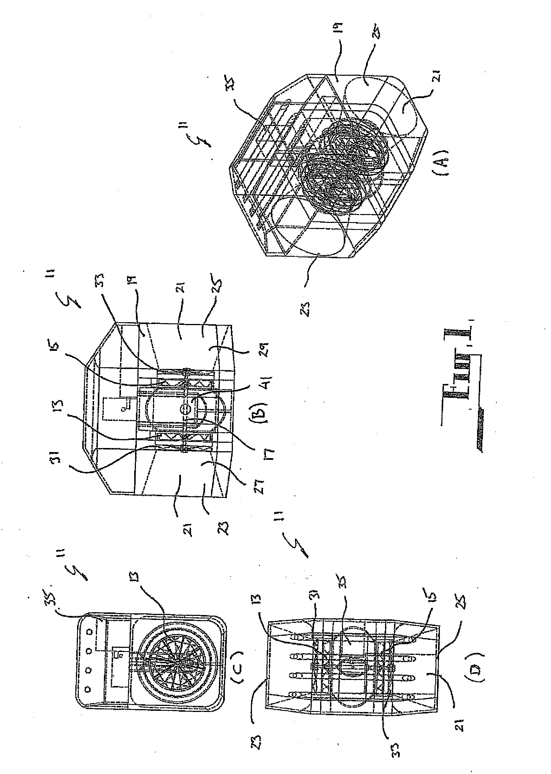
[0099]Referring to FIGS. 1 to 6 the invention according to the invention is in the form of a turbine unit 11. The turbine unit 11 is designed to be located in a fluid flow, and is configured to operate regardless of the direction of flow.

[0100]The turbine unit 11 comprises a first turbine blade set 13 and a second turbine blade set 15 coaxially mounted on a shaft 17.

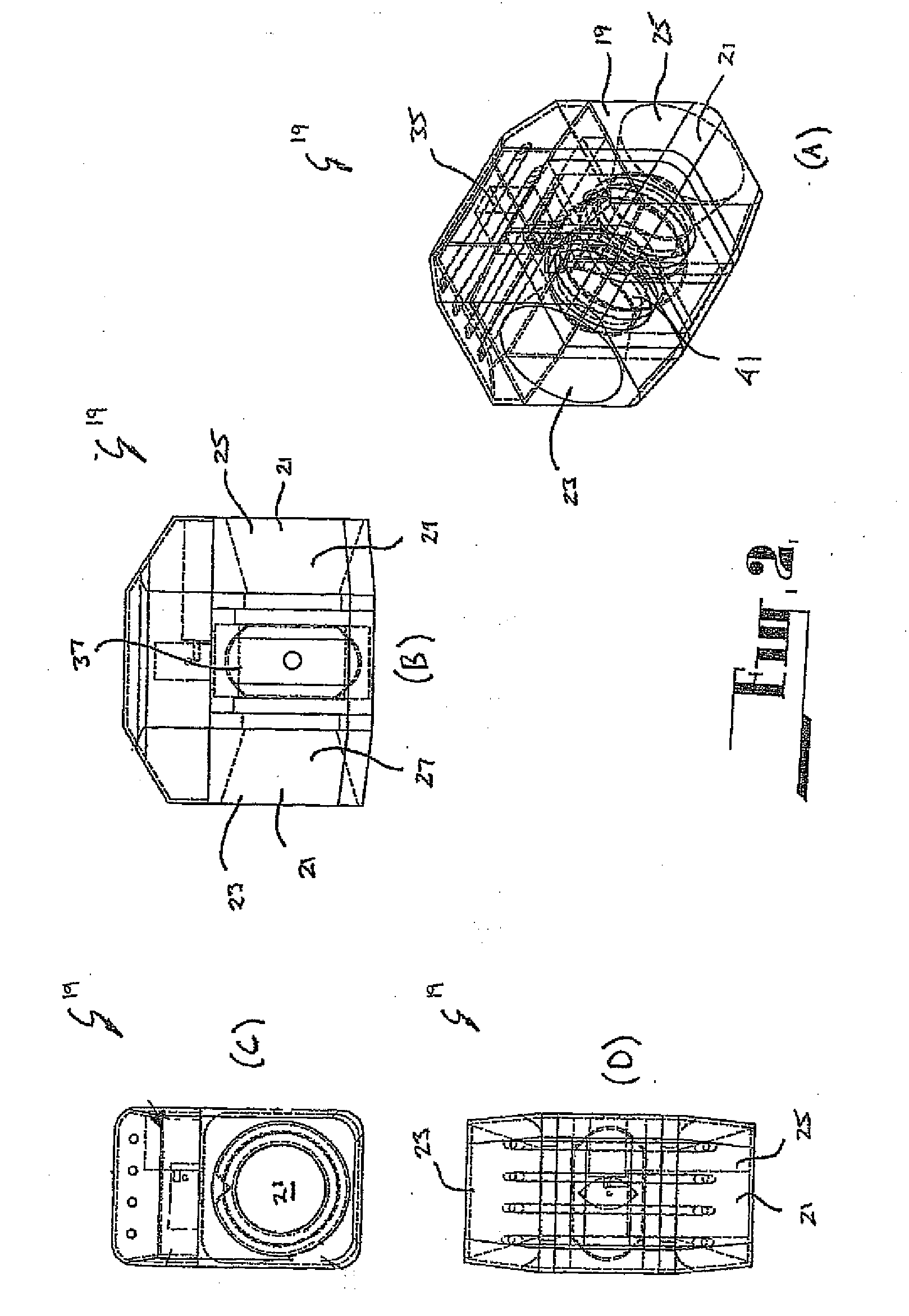
[0101]The first turbine blade set 13 and second turbine blade set 15 are positioned in a passage 21 formed in a housing 19. The passage 21 channels fluid to the first turbine blade set 13 and second turbine blade set 15. Referring to FIG. 2, the passage 21 has a first end 23 and a second end 25. The passage 21 also incorporates a first nozzle 27 located between the first end 23 and the first turbine blade set 13, and a second nozzle 29 located between the second turbine blade set 15 and the second end 25.

[0102]The housing 19 houses a first stator set 31 and a second stator set 33. The first stator set 31 is located in cl...

second embodiment

[0115]Referring to FIG. 7 the invention is shown. In this embodiment the unit 11 comprises two generators 135 located external to the housing 19 and connected to the turbine blade sets. This application is particularly suited to the large assemblies.

[0116]Needless to say there can be multiple generators connected to the housing 19 or even multiple assemblies connected to a generator.

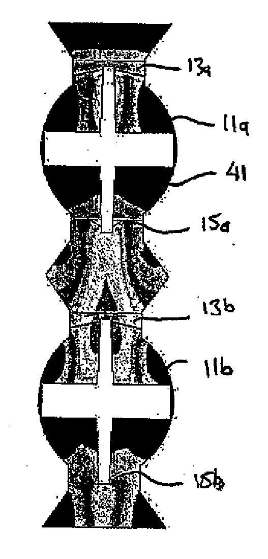
[0117]Referring to FIGS. 8 and 9 a third embodiment of the invention is shown. In this embodiment two turbine units 11 as described in the first embodiment are co-axially arranged in series such that fluid exiting a first turbine unit 11a immediately enters the second turbine unit 11b. In this arrangement the second turbine unit 11b effectively draws the fluid through the first turbine unit 11a, increasing the velocity of the fluid exiting the first turbine unit 11a relative to its velocity before entering the first turbine unit 11a. In the figures numbers having an ‘a’ suffix indicates components of the...

fourth embodiment

[0118]Referring to FIG. 10 the invention is shown. This embodiment is particularly suited to those applications in which the fluid is in the form of a gas.

[0119]In this embodiment a turbine assembly 101 comprises three turbine units 111 in abutment with each other such that they define a passage 121. Each turbine unit 111 comprises a stator 131 which directs fluid onto a driving turbine blade set 113 before the fluid passes to a pumping turbine blade set 115.

[0120]Each unit 111 has a gearbox 137 which is located between the turbine blade sets 113, 115 in a chamber 141.

[0121]The passage 131 interconnecting each turbine unit 111 is straight.

[0122]The turbine assembly 101 has a converging nozzle 127 to accelerate fluid flow as it approaches the first turbine unit 111a. The turbine assembly also has a diverging nozzle 129 to decelerate fluid flow as it exits the end turbine unit 111c.


PUM


Abstract

A turbine unit (11) adapted to be placed in a flowing fluid. The turbine unit (11) comprises a first turbine set (13) and a second turbine set (15) mounted within a passage (21) of a housing (19). The first turbine blade set (13) and a second turbine blade set (15) are set in opposed relation such that in operation a region between the two turbine blade sets (13, 15) has a lower pressure than the fluid pressure at an opening of the passage (21). The turbine unit (11) being used to generate power. The turbine units (FIGS. 8 to 11) can be abutted with each other such that they define a passage and each turbine unit comprises a driving turbine blade set before fluid passes to a pumping turbine blade set.

Description

FIELD OF THE INVENTION[0001]The present invention generally relates to a turbine assembly. In particular the invention relates to a turbine assembly powered by a flowing fluid.BACKGROUND ART[0002]As the demand on earths diminishing fossil fuels increases, research and development of alternative sources of energy is rapidly expanding. To date nuclear energy and renewable energy sources are dominant when considering alternative energy sources.[0003]In relation to nuclear energy there are many significant disadvantages in the use of this fuel: waste disposal / storage, establishment costs and risk of accident, to name but a few.[0004]In relation to renewable energy, such as wind, solar, and wave energy, the cost associated with the establishment of a sufficiently sized plant to harness the energy is, to date, a relatively expensive alternative. Furthermore, the plant only generates energy from these sources if these sources are present. As this is not always the case, the plant may lay i...

Claims


Application Information

Patent Timeline
IPC IPC(8): F03B13/00
CPCF03B13/10F03B13/105F05B2240/133Y02E10/72Y02E10/22F03D1/025F03D1/04F05B2240/97F03D9/25F03D9/28Y02E10/20
Inventor WEST, STEPHEN MARKWEST, STEELE
Owner BRADDELL
Learn More