Method of correcting emissive display burn-in

Inactive Publication Date: 2010-04-29
GOOGLE TECH HLDG LLC
View PDF11 Cites 26 Cited by
  • Summary
  • Abstract
  • Description
  • Claims
  • Application Information

AI Technical Summary

Problems solved by technology

As the burned-in modulation increases, the displa

Method used


Image

  • Method of correcting emissive display burn-in
  • Method of correcting emissive display burn-in
  • Method of correcting emissive display burn-in

Examples


Embodiment Construction

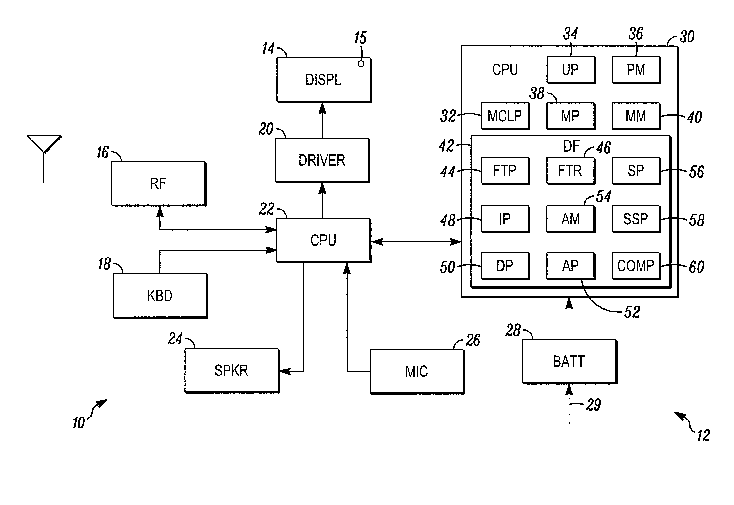
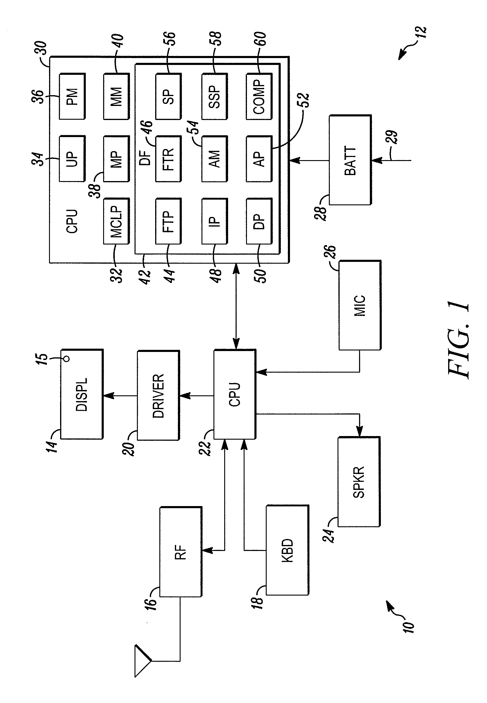
[0027]FIG. 1 shows a portable device (e.g., a cellphone, PDA, etc.) 10 shown generally in accordance with an illustrated embodiment of the invention. Included within the portable device 10 is an emissive display burn-in correction system 12.

[0028]In the case where the portable device 10 is a cellphone, then the portable device 10 may include a radio frequency transceiver 16 for transceiving information with a base station (not shown), a CPU 22 for processing the information and a speaker 24 and microphone 26 for exchanging voice information between a user and the base station.

[0029]The device 10 may also include an emissive display (e.g., OLED, etc.) 14, a driver 20 and a keyboard 18 that operates as a user interface. In this case, the keyboard 18 may be used by a user to enter dialed telephone numbers or to accept incoming calls. Entered numbers and status information may be displayed on the display 14. To display entered numbers and status information, the CPU 22 may activate the ...


PUM


Abstract

A method and apparatus are provided for correcting burn-in in a flat screen display. The method includes the steps of determining a maximum cumulative luminance of each pixel (15) within the display (14) based upon a usage of the pixel, providing a modulation map (40) of the display (14) from the maximum cumulative luminance of each pixel (15) within the display (14), transforming the modulation map (40) based upon the maximum cumulative luminance of groups of adjacent pixels to provide a modulation index for each pixel location of the map (40), comparing the modulation indexes with a set of threshold values and adjusting a luminosity of associated pixels (15) of the display (40) when the modulation index exceeds the threshold.

Description

FIELD OF THE INVENTION [0001]The field of the invention relates to displays and more particularly to a method of correcting burn-in of emissive display devices.BACKGROUND OF THE INVENTION [0002]The use of emissive displays such as organic light emitting diodes (OLEDs) on portable telephones and data devices are well known. Such displays allow an operating system within the telephone or data device to display status of operation and data to a user.[0003]In the case of incoming calls, the display may inform the user of the identity of a caller. In the case of outgoing calls, the display may provide the user with an entered telephone number in order to allow the user to correct mistakes.[0004]In the case of a portable device, the display may show a battery monitor that indicates a battery charge status. As the battery reaches a critical level the battery monitor may flash to notify the user of the need to recharge or suspend use.[0005]In the case of portable telephones or data devices,...

Claims


Application Information

Patent Timeline
IPC IPC(8): G09G5/10
CPCG09G3/30G09G3/3208G09G2320/048G09G2320/046G09G2320/0285G09G3/20
Inventor POLAK, ROBERT D.CADY, ANDREW N.ISHIKAWA, TOMOHIRO
Owner GOOGLE TECH HLDG LLC
Why Eureka
Try Eureka