Microscope apparatus

Active Publication Date: 2010-04-29
EVIDENT CORP
View PDF14 Cites 8 Cited by
  • Summary
  • Abstract
  • Description
  • Claims
  • Application Information

AI Technical Summary

Benefits of technology

[0008]The present invention can provide a microscope apparatus capable of removing liquid from an observation field of view of a dry objective lens, when an immersion objective lens is switched to the dry objective lens. In addition, the present invention can provide a microscope apparatus capable of the observation of the specimen with the dry objective lens while ensuring a good field of view without the influence of the immersion medium, when an immersion objective lens is switched to the dry objective lens.
[0011]As a result, almost all the liquid filling the space between the immersion objective lens and the slide glass (or cover glass) carrying the specimen is moved to the non-observation region of the dry objective lens together with the immersion objective lens due to the surface tension. Thus, the liquid can be removed from the observation region of the dry objective lens without providing a collection device, such as a pump, and the observation of the specimen can be performed with the dry objective lens while ensuring a good field of view.
[0013]This configuration enables the liquid to be removed from the observation region of the dry objective lens while the contact area of the liquid and the cover glass carrying the specimen is reduced. This can reduce the amount by which the stage and / or the immersion objective lens are / is moved and can increase the efficiency of removing the liquid.
[0016]The present invention provides an advantage in that liquid can be removed from the observation field of view of the dry objective lens, when the immersion objective lens is switched to the dry objective lens. In addition, the present invention provides an advantage in that the specimen can be observed with the dry objective lens while ensuring a good field of view without the influence of the immersion medium, when an immersion objective lens is switched to the dry objective lens.

Problems solved by technology

However, when the immersion objective lens is switched to the dry objective lens to perform observation, liquid remains on a cover glass carrying the specimen, resulting in an inconvenience that a suitable observation field of view cannot be ensured in a dry state.

Method used


Image

  • Microscope apparatus
  • Microscope apparatus
  • Microscope apparatus

Examples


first embodiment

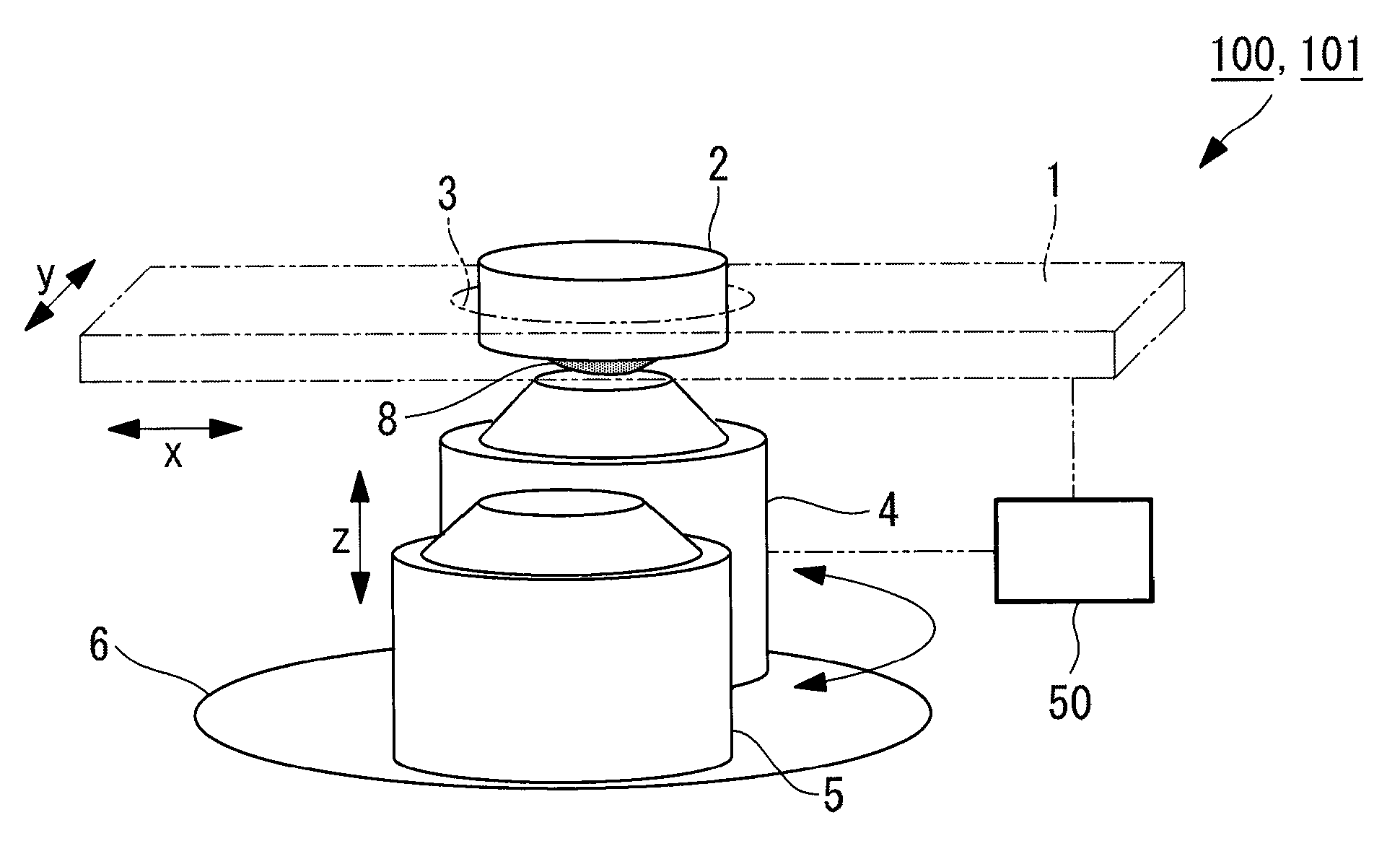
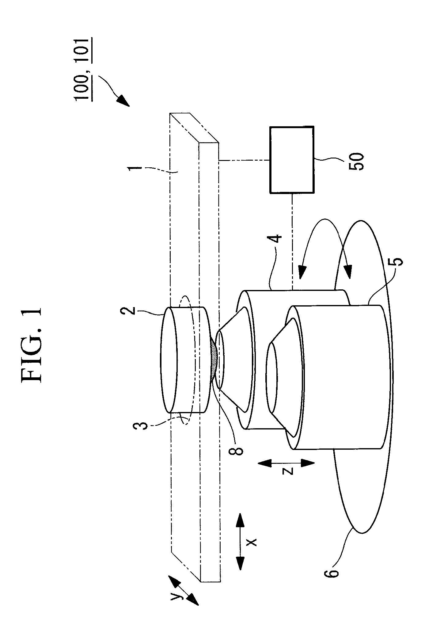
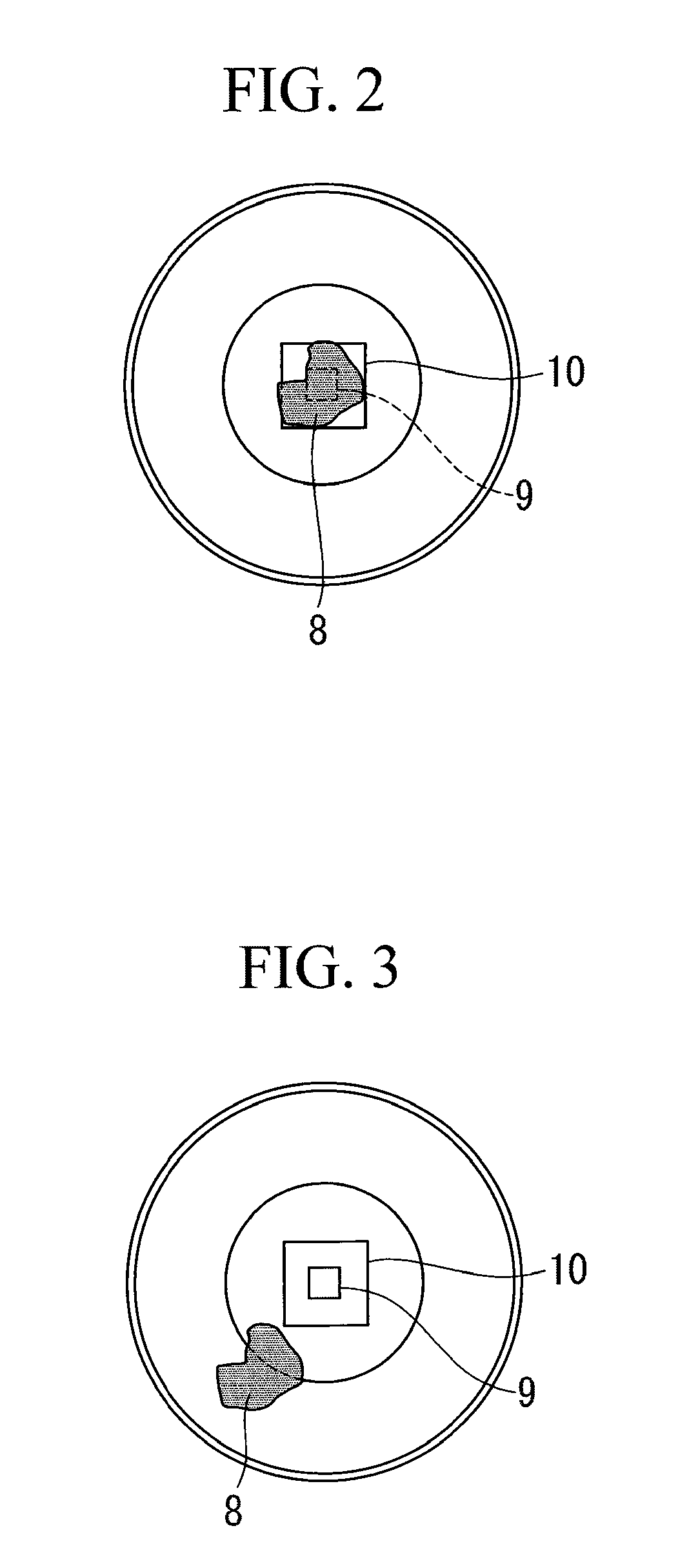
[0030]A microscope apparatus 100 according to a first embodiment of the present invention will be described below with reference to FIGS. 1 to 4.

[0031]FIG. 1 shows, in outline, the structure of the microscope apparatus 100 according to this embodiment. As shown in FIG. 1, the microscope apparatus 100 includes a specimen XY stage 1 on which a specimen is placed, an immersion objective lens 4 and a dry objective lens 5 for collecting light from the specimen, a movable revolver (lens switching portion) 6 that switches between the immersion objective lens 4 and the dry objective lens 5, and a control unit 50 for controlling the specimen XY stage 1 and the movable revolver 6.

[0032]The specimen XY stage 1 includes a container holding portion 3 that holds a specimen container 2 containing the specimen, and is movable in directions (XY directions) perpendicular to the optical axes of the immersion objective lens 4 and the dry objective lens 5 in accordance with a command from the control un...

second embodiment

[0053]A microscope apparatus according to a second embodiment of the present invention will be described below with reference to FIGS. 5 to 7.

[0054]A microscope apparatus 101 according to this embodiment differs from that according to the first embodiment in that, after the relative positions of the specimen XY stage 1 and the immersion objective lens 4 are changed in the Z direction to such a distance that the liquid 8 filling the space between the immersion objective lens 4 and the cover glass 7 does not separate, the relative positions thereof are changed in the XY directions. The microscope apparatus 101 according to this embodiment will be explained below focusing on the parts that differ from the first embodiment, while an explanation about the parts common to the first embodiment will be omitted. Since the structure of the apparatus is the same as that according to the first embodiment shown in FIG. 1, the same reference numerals as the first embodiment will be used for expla...

third embodiment

[0062]A microscope apparatus according to a third embodiment of the present invention will be described below with reference to FIGS. 8 to 10.

[0063]A microscope apparatus 102 according to this embodiment differs from those according to the first and second embodiments in that the liquid 8 having moved to the non-observation region of the dry objective lens 5 is removed. The microscope apparatus 102 according to this embodiment will be explained below focusing on the parts that differ from the first and second embodiments, while an explanation about the parts common to the first and second embodiments will be omitted.

[0064]As shown in FIG. 8, the microscope apparatus 102 includes, in addition to the structure shown in FIG. 1, a suction unit (removal portion) 11, such as a pump, for removing the liquid 8, provided in the non-observation region of the dry objective lens 5. The suction unit 11 includes, at the tip thereof, a suction portion 11a, such as a suction nozzle or a liquid abso...


PUM


Abstract

A microscope apparatus capable of removing liquid from an observation field of view of a dry objective lens, when an immersion objective lens is switched to the dry objective lens, is provided. The microscope apparatus includes a specimen XY stage on which a specimen is placed, a dry objective lens and an immersion objective lens that collect light from the specimen, a movable revolver that selectively disposes one of these objective lenses at a position facing the specimen, and a control unit that controls the specimen XY stage and movable revolver such that the relative positions in the XY direction are changed until the immersion objective lens is disposed at a non-observation region of the dry objective lens, prior to switching of these objective lenses.

Description

BACKGROUND OF THE INVENTION[0001]1. Field of the Invention[0002]The present invention relates to a microscope apparatus including an immersion objective lens and a dry objective lens.[0003]This application is based on Japanese Patent Application No. 2008-275953, the content of which is incorporated herein by reference.[0004]2. Description of Related Art[0005]Conventionally, immersion microscopes used by filling the space between the tip of the objective lens and a specimen with liquid are known (for example, see Japanese Unexamined Patent Applications, Publication Nos. 2004-70307 and 2007-133077). Because such immersion microscopes have high effective numerical apertures (NAs), the resolution of detection optical systems can be increased.[0006]Meanwhile, there is a market demand by people who want to perform macro observation on the same specimen using a low-magnification dry objective lens used in a dry state, after performing high-magnification observation on a local region using ...

Claims


Application Information

Patent Timeline
IPC IPC(8): G02B21/26
CPCG02B21/248G02B27/0006G02B21/33
Inventor KIMURA, HIROYUKI
Owner EVIDENT CORP
Why Eureka
Try Eureka