

Molding process and products formed thereby
- Summary
- Abstract
- Description
- Claims
- Application Information
AI Technical Summary
Benefits of technology
Problems solved by technology
Method used
Image

Examples
first embodiment
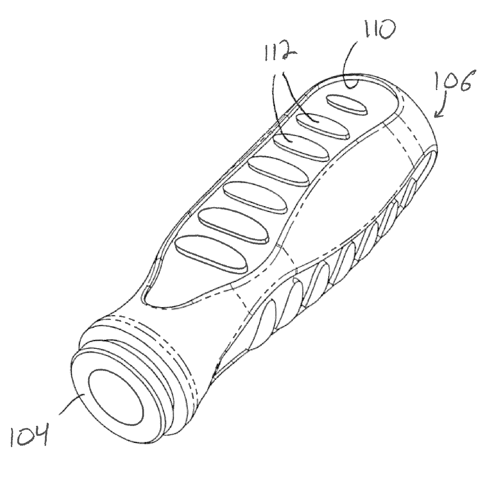
[0027]In a first embodiment illustrated in FIGS. 1-4, the second component 108 is formed separately from the handle 102 including the core 104 and the first component 106. The second component 108 is formed of the desired material to have a shape that is directly complementary to a portion of the first component 106. Preferably, the second component 108 is formed to be an insert positioned within a recess 110 formed in the exterior of the first component 106. The recess 110 can have any desired shape and / or configuration, such as including a number of projections 112 therein, and the second component 108 is formed to be directly complementary to that shape for the recess 110, such as by having a number of apertures 114 formed therein through which the projections 112 can extend.
[0028]In this embodiment, the second component 108 is affixed within the recess 110 of the first component 106 in any suitable manner, such as by mechanically fixing the second component 108 therein, such as ...
second embodiment
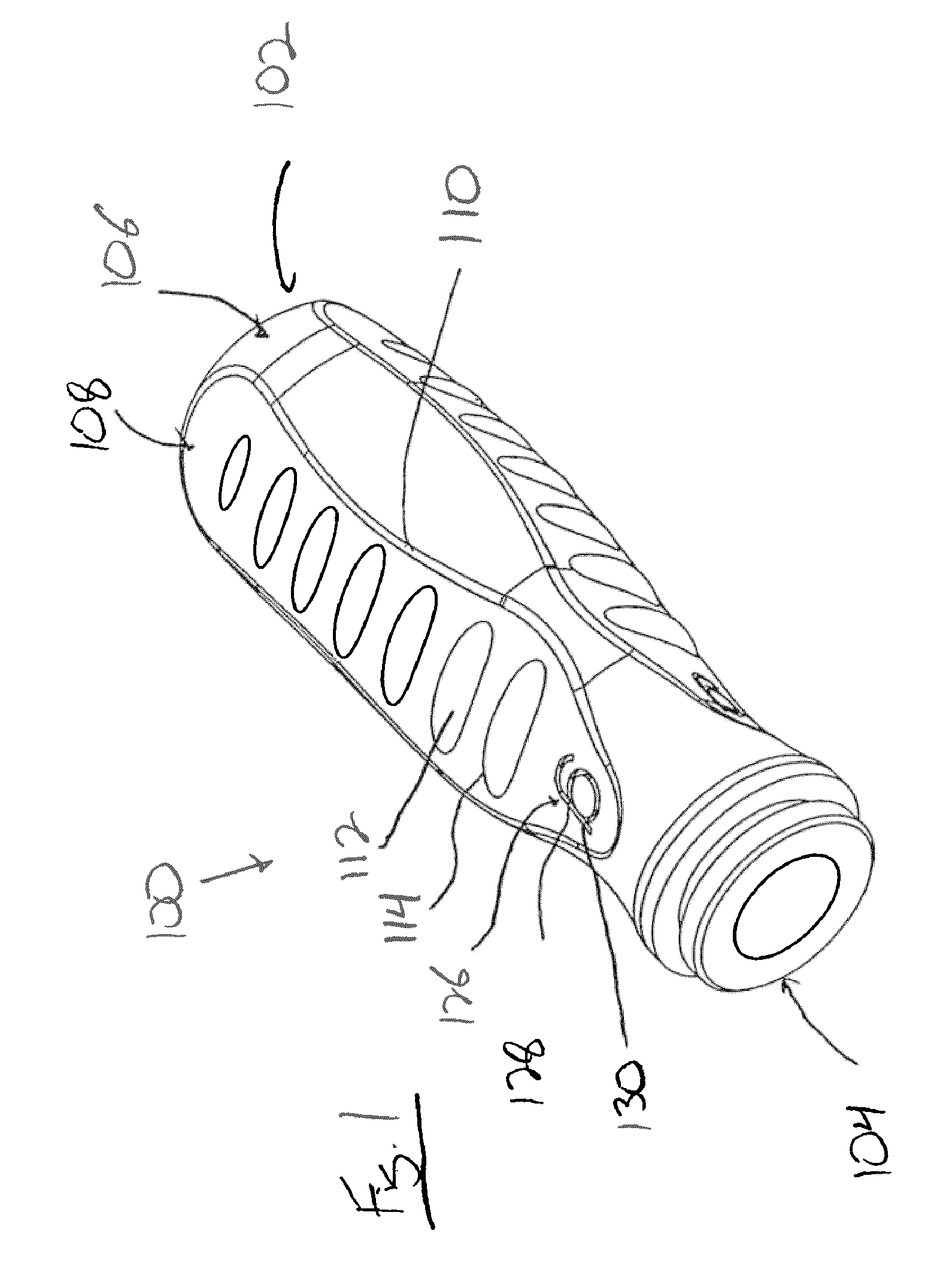
[0031]In this second embodiment, the number of projections 116 formed on the first component 106 can be varied as necessary or desired, depending upon the shape of the item 100 and the desired appearance for the item 100.
[0032]Additionally, in each of the above embodiments, the exposed portions of each of the first component 106 and second component 108 can include indicia 126 positioned thereon or therein. The indicia 126 can be formed directly into the respective first component 106 or the second component 108 during the molding process for these components, or can be formed as a third component 127 that is inserted within a complementary recess 128 disposed in the component 106 or 108.
[0033]In the configuration where the indicia 126 are formed directly within the component 106 and / or 108, preferably the indicia 126 are formed as a raised or recessed section 130 of the component 106 and / or 108. After formation, the section 130 can be further treated, such as by painting or placing...
PUM
| Property | Measurement | Unit |
|---|---|---|
| Time | aaaaa | aaaaa |
| Radius | aaaaa | aaaaa |
| Radius | aaaaa | aaaaa |
Abstract
Description
Claims
Application Information