Supercharge Your Innovation With Domain-Expert AI Agents!

Inflating nozzle assembly

a technology of nozzle assembly and nozzle body, which is applied in the direction of check valves, valve arrangements, thin material handling, etc., can solve the problems of high manufacturing cost, inconvenient use, and complicated structure of conventional nozzle assembly, and achieve excellent leakage-proofing effect, simple structure, and convenient use.

Active Publication Date: 2010-05-13
WANG WEI CHI
View PDF11 Cites 5 Cited by
  • Summary
  • Abstract
  • Description
  • Claims
  • Application Information

AI Technical Summary

Benefits of technology

[0010]The main objective of the invention is to provide an inflating nozzle assembly that is versatile and convenient in use and has a simplified structure and an excellent leakage-proofing effect. The inflating nozzle assembly comprises a housing, two nozzles and a pushing device. The housing is hollow and has an outlet end, a pushing end, two nozzle chambers, an inlet and two outlets. The pushing end is opposite to the outlet end. The nozzle chambers include a first nozzle chamber and a second nozzle chamber formed in the housing and communicating with each other. The inlet is defined in the housing and communicates with the first nozzle chamber. The outlets include a first outlet and a second outlet formed in the outlet end of the housing and communicating respectively with the first and second nozzle chambers. The first nozzle is mounted in the first nozzle chamber and comprises a first resilient holder, a first nozzle body, a nozzle rod and a spring. The first resilient holder is mounted in the first nozzle chamber and has a first passage communicating with the first outlet. The first nozzle body is connected to the first resilient holder, is mounted in the first nozzle chamber and has an axial hole and at least one inlet. The axial hole is defined axially through the first nozzle body and has an inner surface. The at least one inlet is defined radially in the first nozzle body and communicates with the inlet in the housing and the axial hole in the first nozzle body. The nozzle rod is movably mounted in the axial hole in the first nozzle body and has a sealing protrusion. The

Problems solved by technology

A conventional nozzle can only be applied to a specific air valve for inflating an object, such as a ball, a tire or the like, so different types of nozzles must be prepared and carried for different uses, which is inconvenient in use.
1) The switching lever (84) is a necessary element for the conventional nozzle assembly to selectively push one of the nozzles (81,82) to close the corresponding outlet (804,806), so the structure of the conventional nozzle assembly is complicated and has a high manufacturing cost.
2) The switching lever (84) is pushed by one nozzle (81,82) that is connected to an air valve and pushes the other to close the corresponding outlet (804,806). If the switching lever (84) is not precise in size or a provided pushing force from the nozzle (81,82) connected to the air valve is not sufficient, the switching lever (84) cannot provide enough force to push the other nozzle (81,82) to completely close the corresponding outlet (804,806) so leakage will occur. Additionally, to keep the switching lever (84) and nozzles (81,82) from being worn off during the movement thereof, the switching lever (84) and the nozzles (81,82) have to be made of wear-resistant material such that the manufacturing costs of the conventional nozzle assembly are high.

Method used


Image

  • Inflating nozzle assembly
  • Inflating nozzle assembly
  • Inflating nozzle assembly

Examples


Embodiment Construction

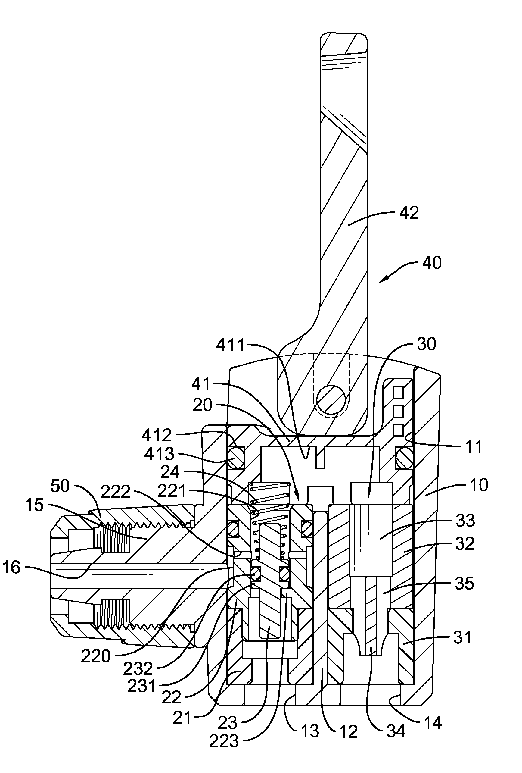
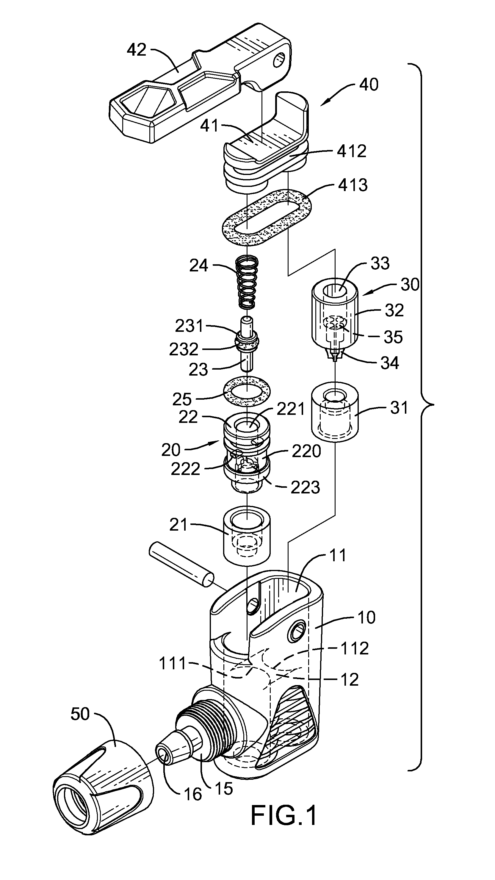
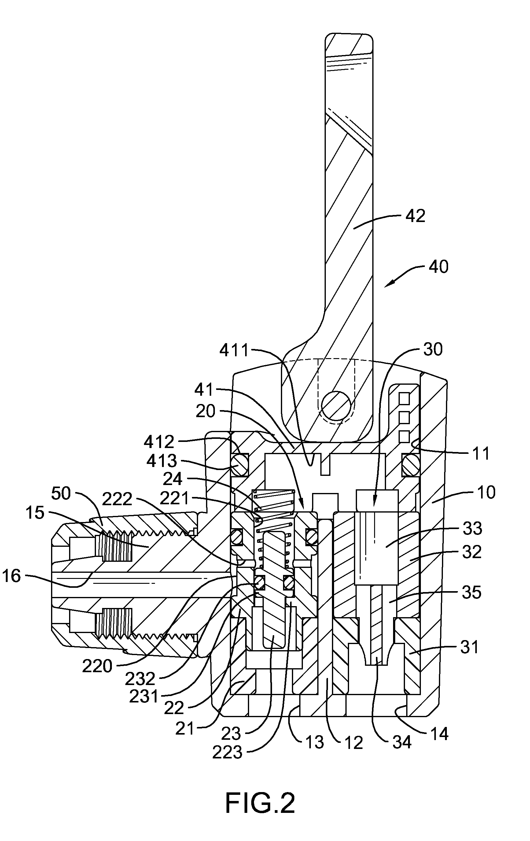
[0017]With reference to FIGS. 1 and 2, an inflating nozzle assembly in accordance with the present invention comprises a housing (10), two nozzles (20,30) and a pushing device (40). The housing (10) is hollow and has an outlet end, a pushing end, a baffle (12), a communication space (11), two nozzle chambers (111,112), an inlet (16), a connecting rod (15), a cap (50) and two outlets (13,14). The pushing end is opposite to the outlet end. The baffle (12) is formed in the housing (10) at the outlet end to divide the housing (10) into the two nozzle chambers (111,112) including a first nozzle chamber (111) and a second nozzle chamber (112). The baffle (12) has a length shorter than that of the housing (10) to form the communication space (11) in the pushing end of the housing (10), which communicates with the nozzle chambers (111,112). With the communication space (11), the first nozzle chamber (111) and the second nozzle chamber (112) communicate with each other. The inlet (16) is def...


PUM


Abstract

An inflating nozzle assembly has a housing, two nozzles and a pushing device. The housing has two nozzle chambers and two outlets. The nozzles are mounted respectively in the first nozzle chamber, and one of the nozzles has a nozzle body, a nozzle rod and a spring. The nozzle body has at least one inlet. The nozzle rod is movably mounted in the nozzle body and has a sealing protrusion to divide two communication segments in the nozzle body. The spring is connected to the nozzle rod to keep one of the communication segments of the axial hole from communicating with the at least one inlet in the first nozzle body. Accordingly, an airflow led through the outlets of the housing can be automatically switched by inserting different types of air valves into the corresponding outlets.

Description

BACKGROUND OF THE INVENTION[0001]1. Field of the Invention[0002]The present invention relates to an inflating nozzle assembly, and more particularly to an inflating nozzle assembly having two nozzles to fit with different types of air valves.[0003]2. Description of Related Art[0004]A conventional nozzle can only be applied to a specific air valve for inflating an object, such as a ball, a tire or the like, so different types of nozzles must be prepared and carried for different uses, which is inconvenient in use.[0005]With reference to FIG. 5, a conventional nozzle assembly that can fit with different types of air valves comprises a housing (80), two nozzles (81,82) and a switching lever (84). The housing (80) has an inlet (802) and two outlets (804,806). The nozzles (81,82) are mounted moveably in the housing (80), have different structures from each other and communicate selectively with the inlet (802) and respectively with the outlets (804,806). The switching lever (84) is mount...

Claims


Application Information

Patent Timeline
IPC IPC(8): F16K15/20
CPCF16K15/20Y10T137/3584Y10T137/3724
Inventor WANG, WEI-CHI
Owner WANG WEI CHI
Features
  • R&D
  • Intellectual Property
  • Life Sciences
  • Materials
  • Tech Scout
  • Unparalleled Data Quality
  • Higher Quality Content
  • 60% Fewer Hallucinations
Learn More