
Method and system for non-destructive determination of dielectric breakdown voltage in a semiconductor wafer

Active Publication Date: 2010-05-13
ADVANCED MICRO DEVICES INC
View PDF3 Cites 12 Cited by
  • Summary
  • Abstract
  • Description
  • Claims
  • Application Information

AI Technical Summary

Benefits of technology

[0005]A method and system for non-destructive determination of dielectric breakdown voltage in a semiconductor wafer, substantia

Problems solved by technology

However, breakdown of a dielectric layer in an IC can cause the IC to fail.
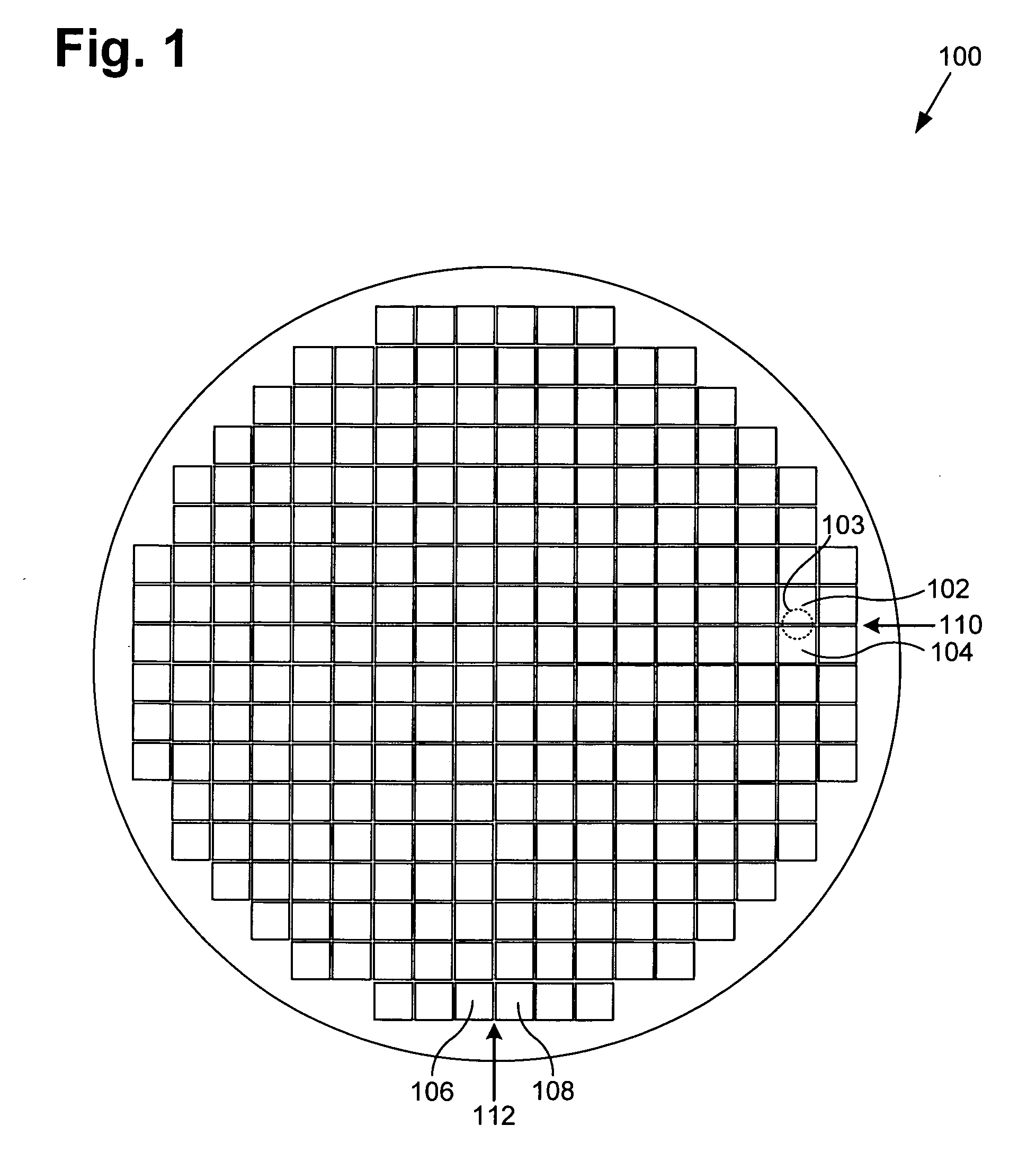
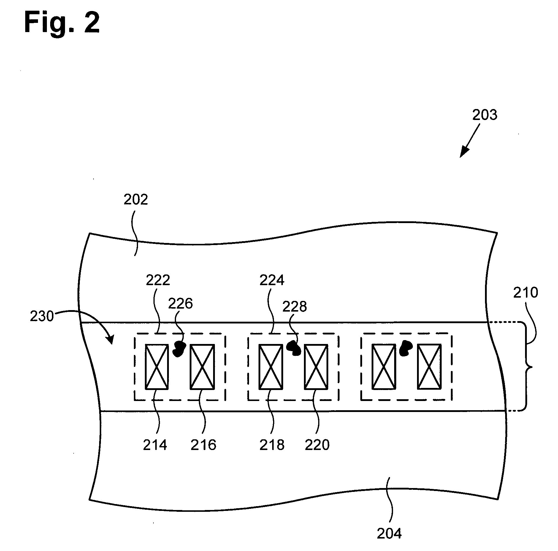
However, in the conventional voltage ramp method, the breakdown of the dielectric layer typically results in a catastrophic failure of the dielectric layer, which causes a bum mark in the dicing street on the wafer.
As a result of uncertainty as to whether the wafer has been contaminated by debris associated with the burn mark, the wafer has to be scrapped.
Thus, although the conventional voltage ramp method can be utilized to determine a breakdown voltage of a dielectric layer, the catastrophic breakdown of the dielectric layer that occurs in the conventional voltage ramp method results in the wafer being scrapped, which undesirably increases manufacturing cost.

Method used


Image

  • Method and system for non-destructive determination of dielectric breakdown voltage in a semiconductor wafer
  • Method and system for non-destructive determination of dielectric breakdown voltage in a semiconductor wafer
  • Method and system for non-destructive determination of dielectric breakdown voltage in a semiconductor wafer

Examples


Embodiment Construction

[0014]The present invention is directed to a method and system for non-destructive determination of dielectric breakdown voltage in a semiconductor wafer. The following description contains specific information pertaining to the implementation of the present invention. One skilled in the art will recognize that the present invention may be implemented in a manner different from that specifically discussed in the present application. Moreover, some of the specific details of the invention are not discussed in order not to obscure the invention.

[0015]The drawings in the present application and their accompanying detailed description are directed to merely exemplary embodiments of the invention. To maintain brevity, other embodiments of the present invention are not specifically described in the present application and are not specifically illustrated by the present drawings. It should be borne in mind that, unless noted otherwise, like or corresponding elements among the figures may b...


PUM


Abstract

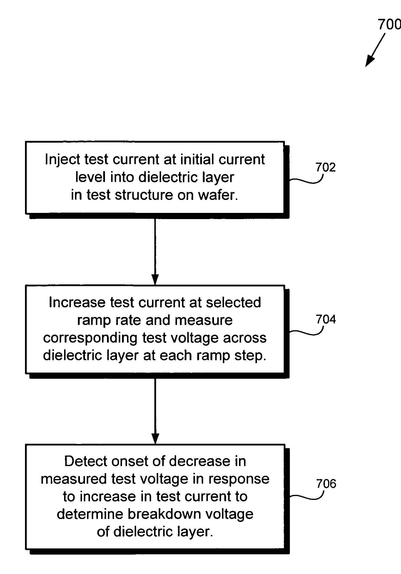
According to one exemplary embodiment, a non-destructive method for determining a breakdown voltage of a dielectric layer on a semiconductor substrate includes injecting a test current in increasing ramp steps into the dielectric layer. The method further includes measuring a test voltage across the dielectric layer at each increasing ramp step of the test current. The method further includes detecting a dropped test voltage in response to the increasing ramp steps of the test current. The ramp steps of the test current can be substantially logarithmically increased. The breakdown voltage of the dielectric layer can be designated to be substantially equal to the dropped test voltage.

Description

TECHNICAL FIELD[0001]The present invention is generally in the field of semiconductor fabrication. More particularly, the invention is in the field of dielectric reliability testing on semiconductor wafers.BACKGROUND ART[0002]During semiconductor wafer fabrication, integrated circuits (ICs) that are formed on the wafer utilize layers of dielectric material, such as silicon dioxide, to provide insulation between adjacent metal segments and layers on the wafer. For example, an inter-level dielectric layer can be utilized to insulate adjacent metal layers on the wafer, while an intra-level dielectric layer can be utilized to insulate adjacent metal segments that are formed in a metal layer. However, breakdown of a dielectric layer in an IC can cause the IC to fail. Consequently, it is important for semiconductor manufacturers to conduct dielectric reliability testing during wafer fabrication. Dielectric reliability testing typically includes determining dielectric breakdown voltage, wh...

Claims


Application Information

Patent Timeline
IPC IPC(8): G01R31/12
CPCG01R31/318511G01R31/1263
Inventor YIANG, KOK YONGFRANCIS, RICKMARATHE, AMIT P.PHAM, VAN-HUNG
Owner ADVANCED MICRO DEVICES INC
Learn More