Image display apparatus and method for controlling the same

Inactive Publication Date: 2010-05-13
CANON KK
View PDF23 Cites 0 Cited by
  • Summary
  • Abstract
  • Description
  • Claims
  • Application Information

AI Technical Summary

Benefits of technology

[0006]The present invention is directed to an image display apparatus capable of eliminat

Problems solved by technology

In this way, in the conventional art, the operations for printing the content displayed on the

Method used


Image

  • Image display apparatus and method for controlling the same
  • Image display apparatus and method for controlling the same
  • Image display apparatus and method for controlling the same

Examples


Example

[0015]Various exemplary embodiments, features, and aspects of the invention will be described in detail below with reference to the drawings.

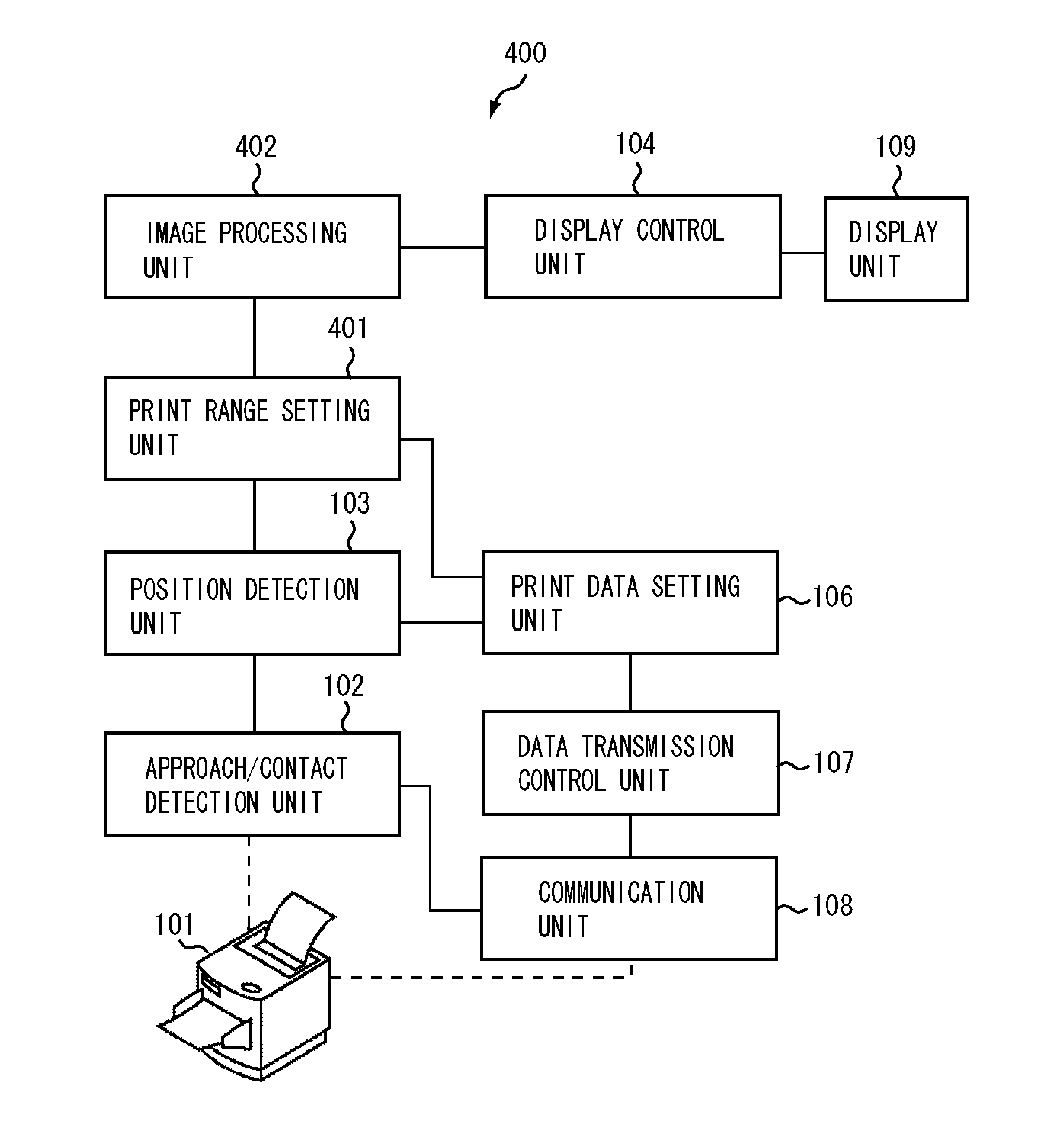
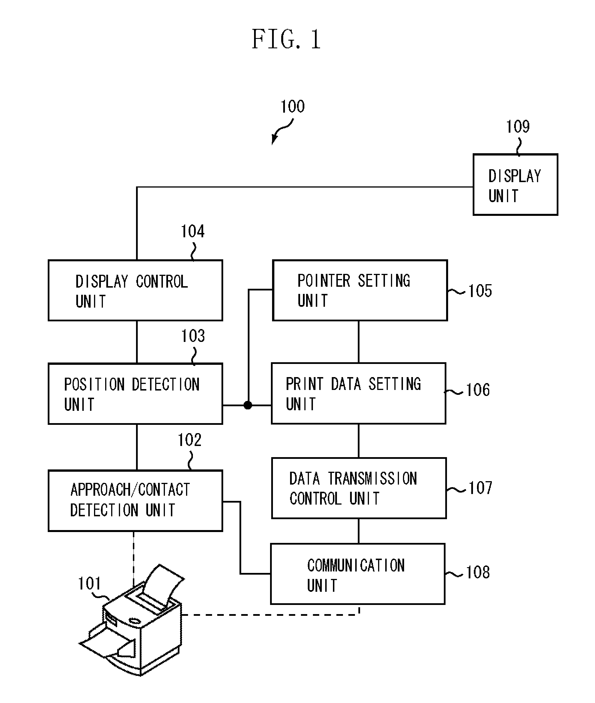
[0016]FIG. 1 is a block diagram illustrating an example of a configuration of an image display apparatus 100 according to a first exemplary embodiment of the present invention. In FIG. 1, a printer 101 as a printing apparatus is a printer, which can be brought close to a display unit 109 by a user. Hence, the printer 101 is preferably a portable, compact printer in the present exemplary embodiment.

[0017]An approach / contact detection unit 102 detects approach of the printer 101 when it is close to the display unit 109. Once the approach / contact detection unit 102 detects approach of the printer 101, it establishes connection with the printer 101 via a communication unit 108. At this time, connection with the printer 101 is performed with use of publicly known wireless communication technique.

[0018]When a position detection unit 103 receives a no...


PUM


Abstract

An image display apparatus includes a control unit configured to display a content on a display unit, a detection unit configured to detect a printing apparatus located at a predetermined distance or less from the display unit, a calculation unit configured to calculate a position on the display unit of the printing apparatus detected by the detection unit, and a transmission unit configured to transmit, to the printing apparatus, data of a content based on the position calculated by the calculation unit among contents displayed on the display unit.

Description

BACKGROUND OF THE INVENTION[0001]1. Field of the Invention[0002]The present invention relates to an image display apparatus, and a method for controlling the image display apparatus, a program, and a storage medium, and particularly to a technique suitably used for printing displayed content.[0003]2. Description of the Related Art[0004]Conventionally, in printing a content displayed on a display unit, a cable or wireless connection equipment is used to connect the printer to a display unit or an information processing apparatus to which the display unit is connected. Then, after the content is selected, print is selected from the menu, a printer is selected and then, printing starts. That is, plural operations are required. To address this, for example, Japanese Patent Application Laid-Open No. 10-283067 discusses a printer-integrated electronic information apparatus that enables easy connection of the printer.[0005]However, in the electronic information apparatus discussed in Japan...

Claims


Application Information

Patent Timeline
IPC IPC(8): G06F3/12
CPCH04W4/02H04L67/16H04L67/18G06F3/1292G06F3/1226G06F3/1285G06F3/1204H04L67/52H04L67/51
Inventor ODAGAWA, MASAYUKI
Owner CANON KK
Why Eureka
Try Eureka