Socket for testing semiconductor package

Active Publication Date: 2010-05-13
HON HAI PRECISION IND CO LTD
View PDF8 Cites 7 Cited by
  • Summary
  • Abstract
  • Description
  • Claims
  • Application Information

AI Technical Summary

Benefits of technology

[0008]An object of the invention is to provide a socket, wh

Problems solved by technology

However, since the foot is soldered onto the printed circuit board

Method used


Image

  • Socket for testing semiconductor package
  • Socket for testing semiconductor package
  • Socket for testing semiconductor package

Examples


Example

[0015]Reference will now be made in detail to the preferred embodiment of the present invention.

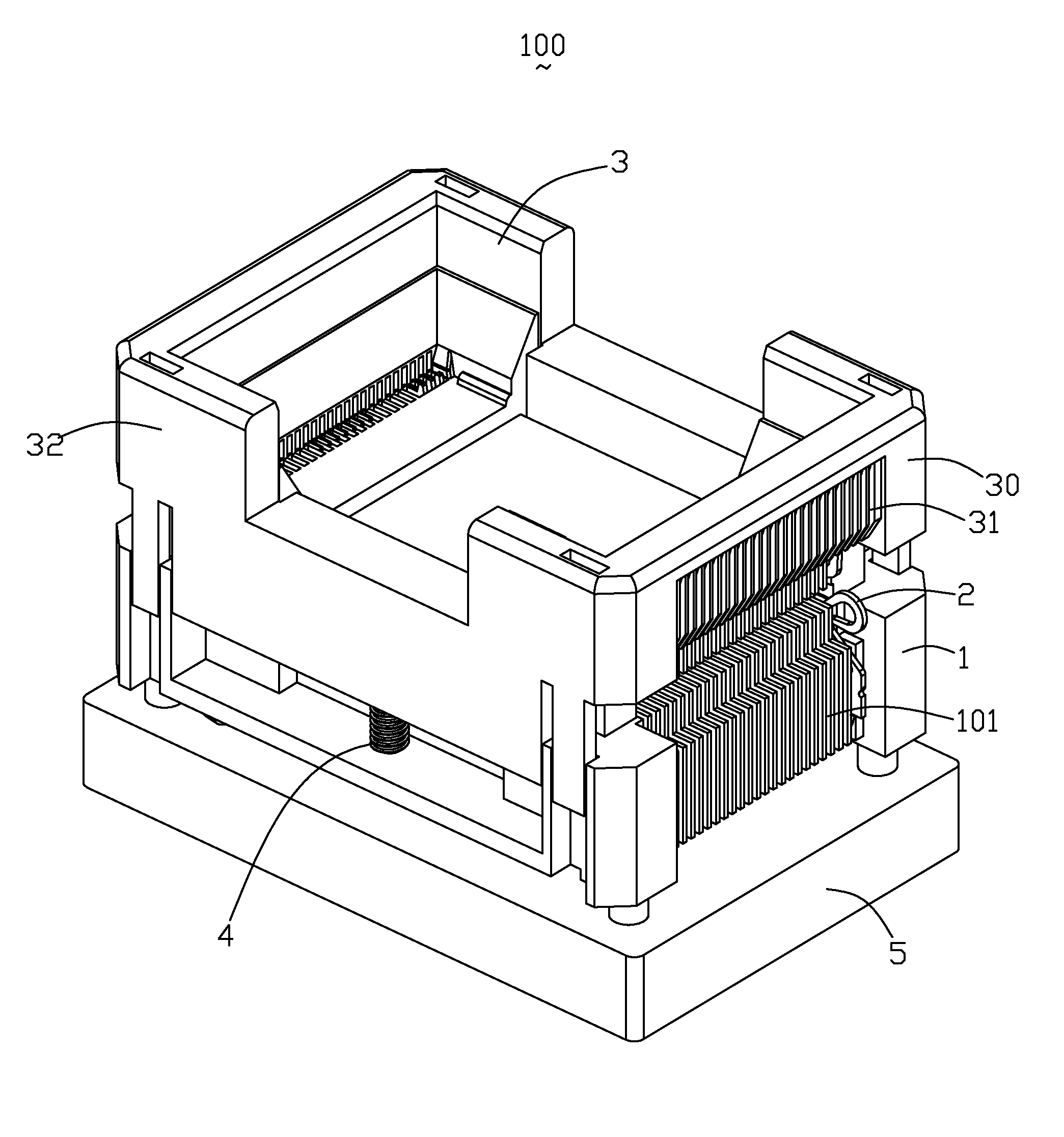
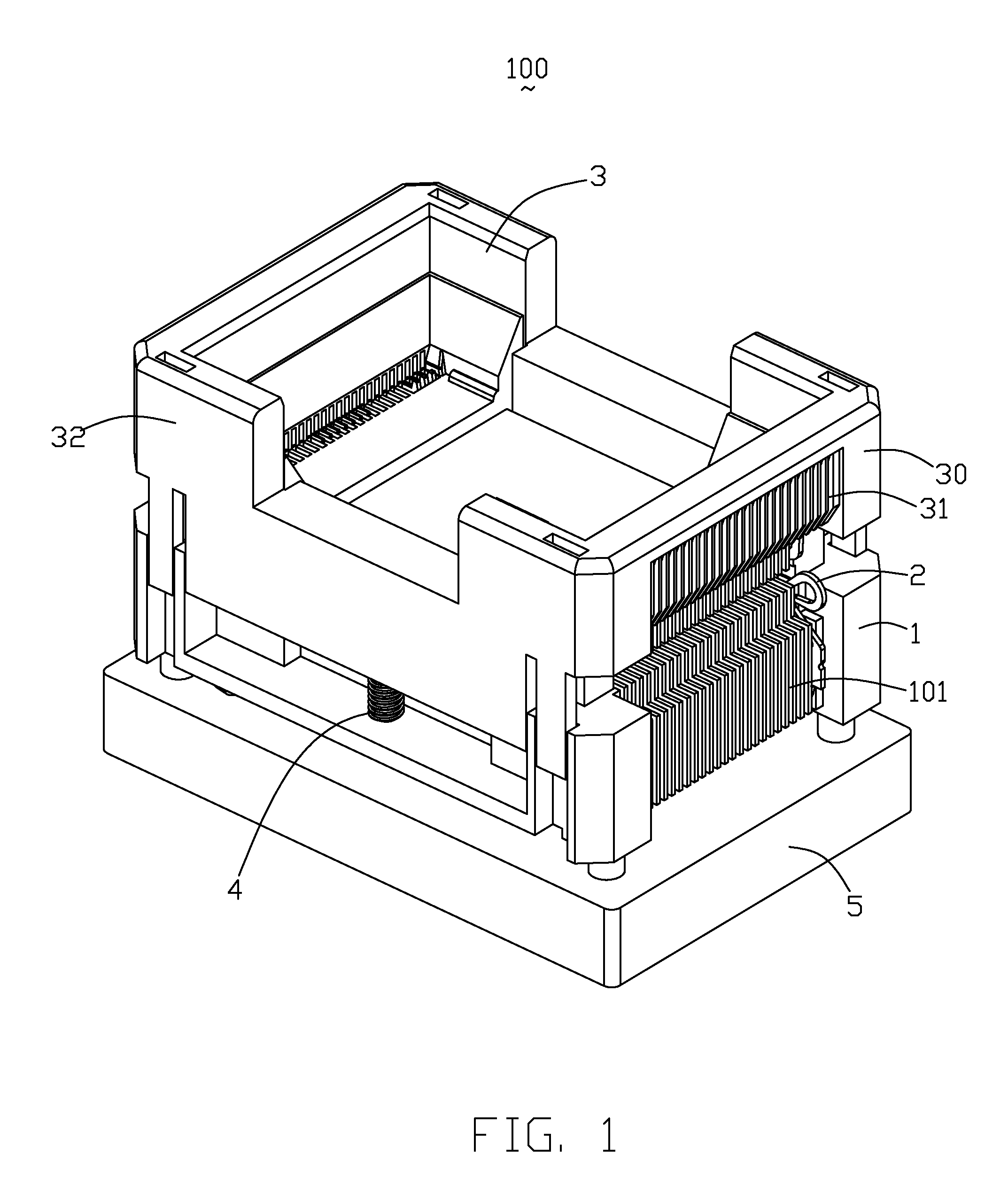
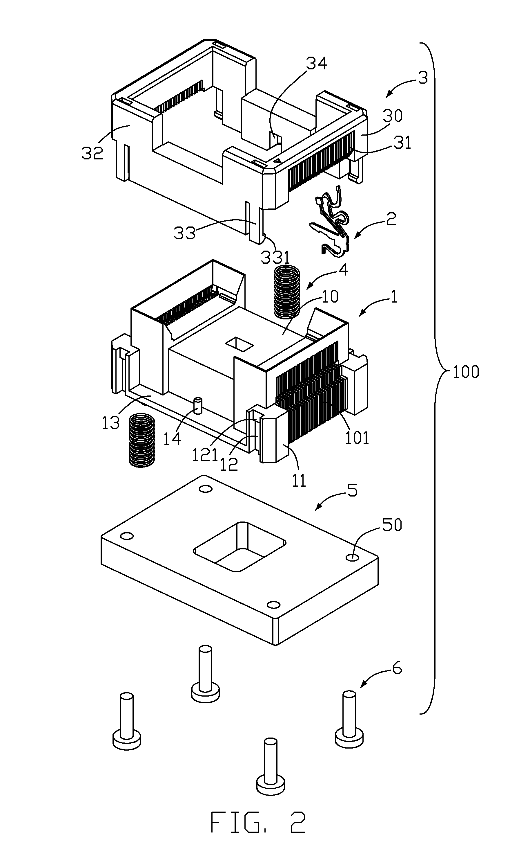
[0016]Referring to FIGS. 1-4, a socket 100, adapted for electrically connecting semiconductor package and printed circuit board, comprises a main body 1, a plurality of contacts 2 received in the main body 1, an operating cover 3 mounted upon the main body 2, a plurality of springs 4, a backplane 5 mounted below the main body 1 and bolts 6 retain the backplane 5 below the main body 1.

[0017]Continue to referring to FIG.2, the main body 1 is configured with a rectangular shape, and is formed with a base 10 along with a plurality of flanges 11 on four corners thereof. Each of the flanges 11 is provided with a channel 12, which guides the operating cover 3 to move upwardly and downwardly with respect to the main body 1 and has a protrusion 121 therein for retaining the operating cover 3 to the main body 1, the main body 1 defines a plurality of contact passageways 101 for receiving the contac...


PUM


Abstract

A socket adapted for electrically connecting a semiconductor package to a printed circuit board, includes a main body defining a number of contact passageways and a plurality of contacts received in the contact passageways of the main body. Each contact has a base portion, a first contacting portion and a second contacting portion upwardly extending from the base portion, and a spring arm bent from a bottom edge of the base portion. The spring arm extends substantially in a horizontal direction and is bent downwardly at a free end thereof to form a tail. The spring arm can deform to provide an elastic force for the tail to press against the printed circuit board.

Description

BACKGROUND OF THE INVENTION[0001]1. Field of the Invention[0002]The present invention relates to a socket, and more particularly to a socket being soldered to a printed circuit board and adapted for testing a semiconductor package.[0003]2. Description of the Related Art[0004]European Patent Application No. 1091628 discloses a typical socket of the like, which includes a main body, an operating cover and a plurality of contacts accommodated in the main body. The main body has a plurality of retaining holes. The operating cover is formed with a cam surface. The contact is integrally stamped from a metal sheet and includes a retaining leg engaging with the retaining hole of the main body, a body leg linking with a side of the retaining leg, a foot downwardly extending from a side of the body leg and a first and a second contacting portions disposed on another side of the body leg. The first contacting portion has an elastic portion, a first contacting arm, a haulm portion, a top end an...

Claims


Application Information

Patent Timeline
IPC IPC(8): H01R12/00
CPCG01R1/0466H05K7/1053H01R13/2435H01R13/2428
Inventor HSIAO, SHIH-WEILIN, WEI-CHIH
Owner HON HAI PRECISION IND CO LTD
Why Eureka
Try Eureka