Plate implant, in particular for use on a spinal column

Inactive Publication Date: 2010-05-13
ULRIKH GMBKH & KO KG
View PDF11 Cites 46 Cited by
  • Summary
  • Abstract
  • Description
  • Claims
  • Application Information

AI Technical Summary

Benefits of technology

[0014]Another advantage of the invention is that with respect to its guide element the plate implant is designed such that when the plate implant is displaced elements of this implant do not slide across the vertebra or bone. This advantageously minimizes irritation to the periosteum.

Problems solved by technology

In particular when the plate implants are being fastened there is the problem that as a rule the spacing between consecutive vertebras is frequently different so that a number of plate implants of different lengths must be kept in stock in different embodiments.

Method used


Image

  • Plate implant, in particular for use on a spinal column
  • Plate implant, in particular for use on a spinal column
  • Plate implant, in particular for use on a spinal column

Examples


Embodiment Construction

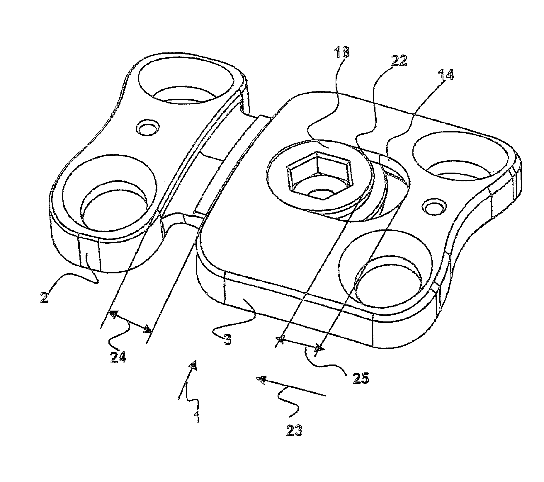
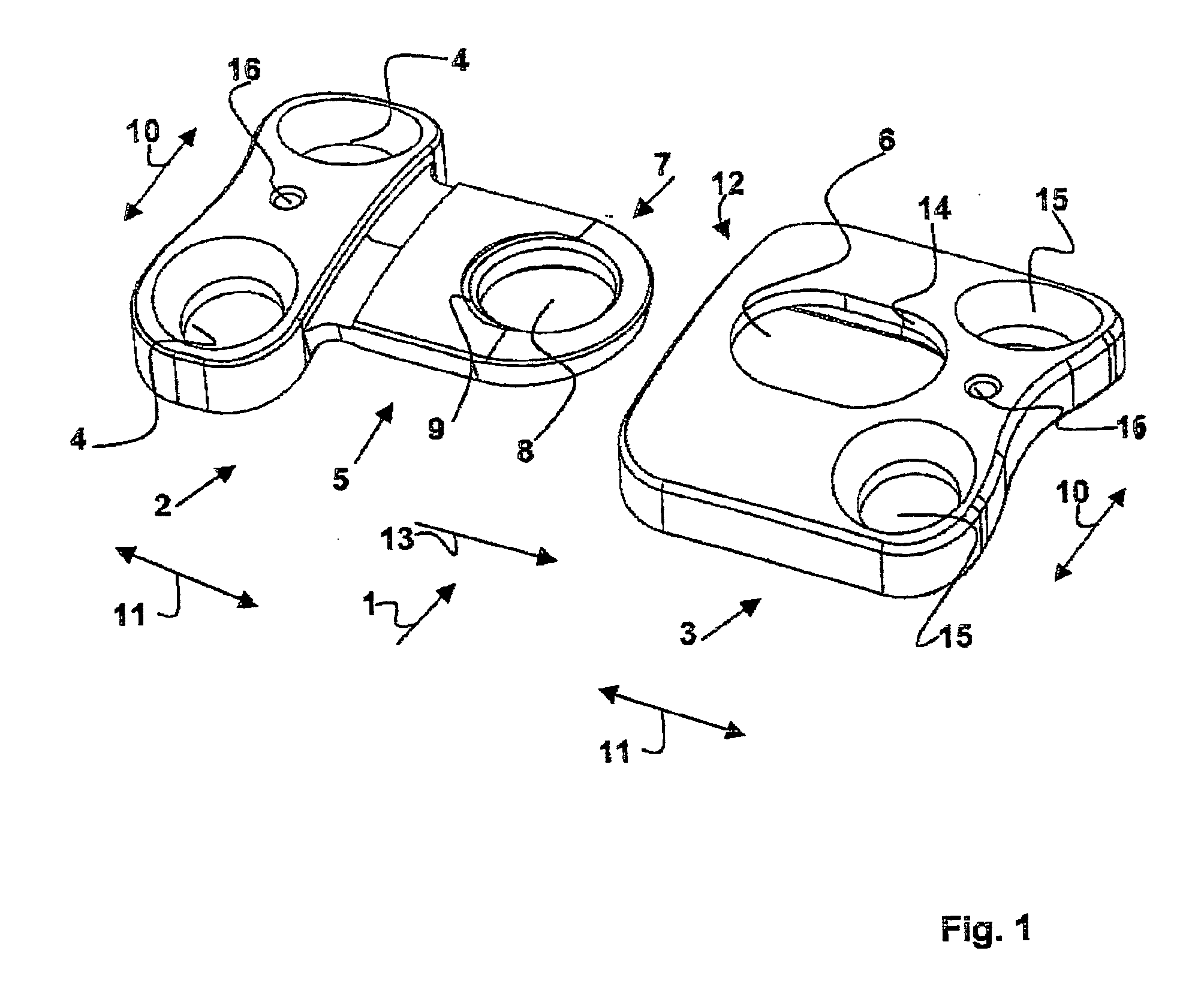
[0046]FIG. 1 illustrates the basic principle of the plate implant 1. This plate implant 1 comprises a first end plate 2 and another end plate 3. The two end plates 2 and 3 have different shapes.

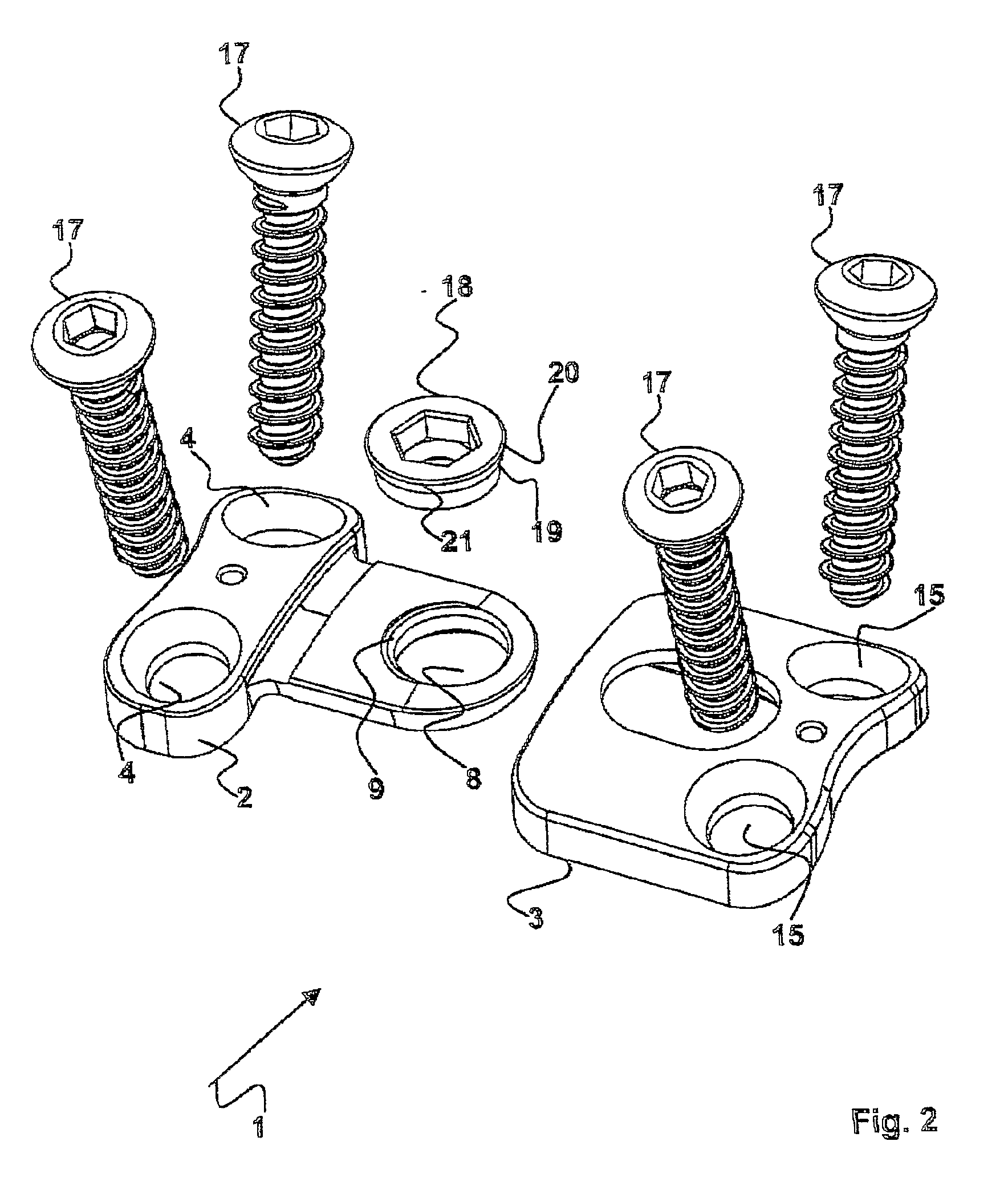
[0047]The first plate 2 has bores 4 for fastening screws (not shown in greater detail). Furthermore, a connector 5 is provided that fits in a seat 6 for the other, second plate 3. The connector 5 is shaped like a tongue and its cross-section is smaller than the other element of the plate 2. The connector 5 is also not as thick as the other element of the plate 1.

[0048]A bore 8 is provided on the outer end 7 of the connector 5. This bore 8 preferably also has a female screwthread 9.

[0049]The first plate 2 is curved both in the direction 10 of its transverse extension and in the direction 11 of its longitudinal extension so that it can be fitted to a vertebra or bone.

[0050]As stated above, the tongue-like connector 5 is designed to fits in the seat 6 of the second plate 3. To this end the secon...


PUM


Abstract

The invention relates to a plate-implant for use in osteosynthesis, comprising at least one first plate component with throughbores for receiving fastening screws and a connection means, at least one second plate component with throughbores for receiving fastening screws and a receiving means for receiving a connection means. According to the invention, each plate component is slidable in one direction relative to the other plate component, the plate components being provided with a device limiting their slide path relative to each other. The device comprises a clamping screw (18) having a thread and a screw head and, in the mounted state of the two plate components (2, 3), the thread cooperates with the connection means (5) and the screw head with a longitudinal borehole (14) provided in the second plate component (3) in such a way that a clamping effect is obtained between the screw head and the longitudinal borehole (14) and between the connection means (5) and the receiving means (6).

Description

TECHNICAL FIELD[0001]The invention relates to a plate implant that in its basic configuration comprises a first plate and a second plate. The first plate has bores for receiving fastening screws and a connector. The other, second plate has a seat for receiving a connector and bores for receiving fastening screws. Each of the plates is borne slidable in one direction relative to the other plate and the plates are provided with formations that limit their sliding relative to one another.PRIOR ART[0002]Osteosynthesis is a method for treating bone fractures and other bone injuries in which in particular implants that comprise metal are used. The goal is to fix the position of the bone fragments that belong together in a normal position (repositioning). As a rule surgical care involves attaching metal plates and fastening screws to the bone or, in particular for fractures of the shaft of the major long bones, it involves inserting long rods that fit in the medullary cavity along the axis...

Claims


Application Information

Patent Timeline
Patent Type & Authority Applications(United States)
IPC IPC(8): A61B17/80
CPCA61B17/7059A61B2019/444A61B17/8023A61B90/92A61B17/70A61B17/80
Inventor REITZIG, CLIFF-GEORGECKHOF, STEPHENSCHWEIZER, BARBARA
Owner ULRIKH GMBKH & KO KG
Why Eureka
Try Eureka