
Manufacturing apparatus of absorbent article and manufacturing method of absorbent article

Active Publication Date: 2010-05-20
UNI CHARM CORP
View PDF7 Cites 11 Cited by
  • Summary
  • Abstract
  • Description
  • Claims
  • Application Information

AI Technical Summary

Benefits of technology

[0010]Then, the present invention has been made in light of such a situation. An object of the present invention is to provide a manufacturing apparatus of an absorbent article and a manufacturing method of an absorbent article in which generation of wrinkles and poor transfer can be prevented so that a work such as an absorbent sheet can adhere to a web more securely when the work is to adhere to the web under conveyance.
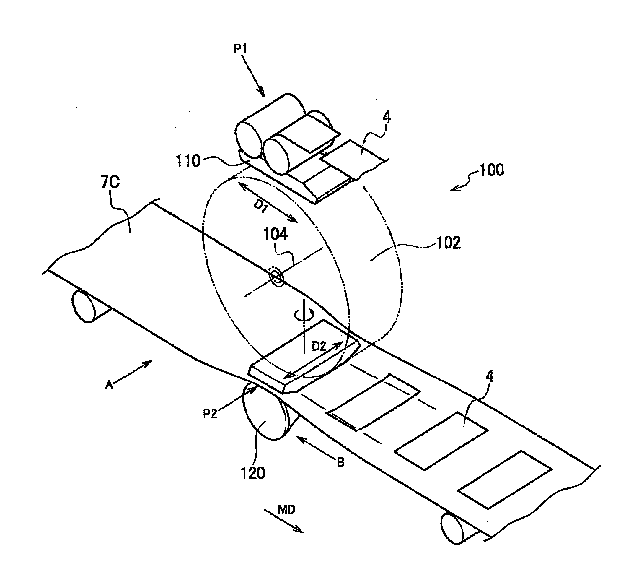
[0013]Accordingly, when causing the work to adhere to the web under conveyance, the manufacturing apparatus of the absorbent article can prevent generation of wrinkles and poor transfer, and can cause the work to adhere to the web more securely.
[0023]According to the aspects of the present invention, the manufacturing apparatus of the absorbent article and the manufacturing method of the absorbent article can be provided in which generation of wrinkles and poor transfer can be prevented and a work such as an absorbent sheet can adhere to the web more securely when the work is to adhere to the web under conveyance.

Problems solved by technology

However, the above-mentioned conventional manufacturing apparatus of the absorbent article has the following problems.
Specifically, since the adsorbing face of the adsorbing pad is formed into the shape in which its outer edge portions are inclined toward the shaft center side of the rotation drum, problems arise such that wrinkles would appear in the absorbent sheet and the absorbent sheet deviates from the predetermined position on the web.
This is because, when the adsorbing pad passes the absorbent sheet to the web with an adhesive applied thereon, the absorbent sheet adsorbed by the central portion of the adsorbing face firmly adheres to the web, while the absorbent sheet adsorbed by each outer edge portion is difficult to adhere firmly to the web.
In this case, since the absorbent sheet adsorbed by each outer edge portion is difficult to adhere firmly to the web, similar to the above-mentioned, problems arise such that wrinkles occur in the absorbent sheet and the absorbent sheet deviates from the predetermined position on the web.

Method used


Image

  • Manufacturing apparatus of absorbent article and manufacturing method of absorbent article
  • Manufacturing apparatus of absorbent article and manufacturing method of absorbent article
  • Manufacturing apparatus of absorbent article and manufacturing method of absorbent article

Examples


first embodiment

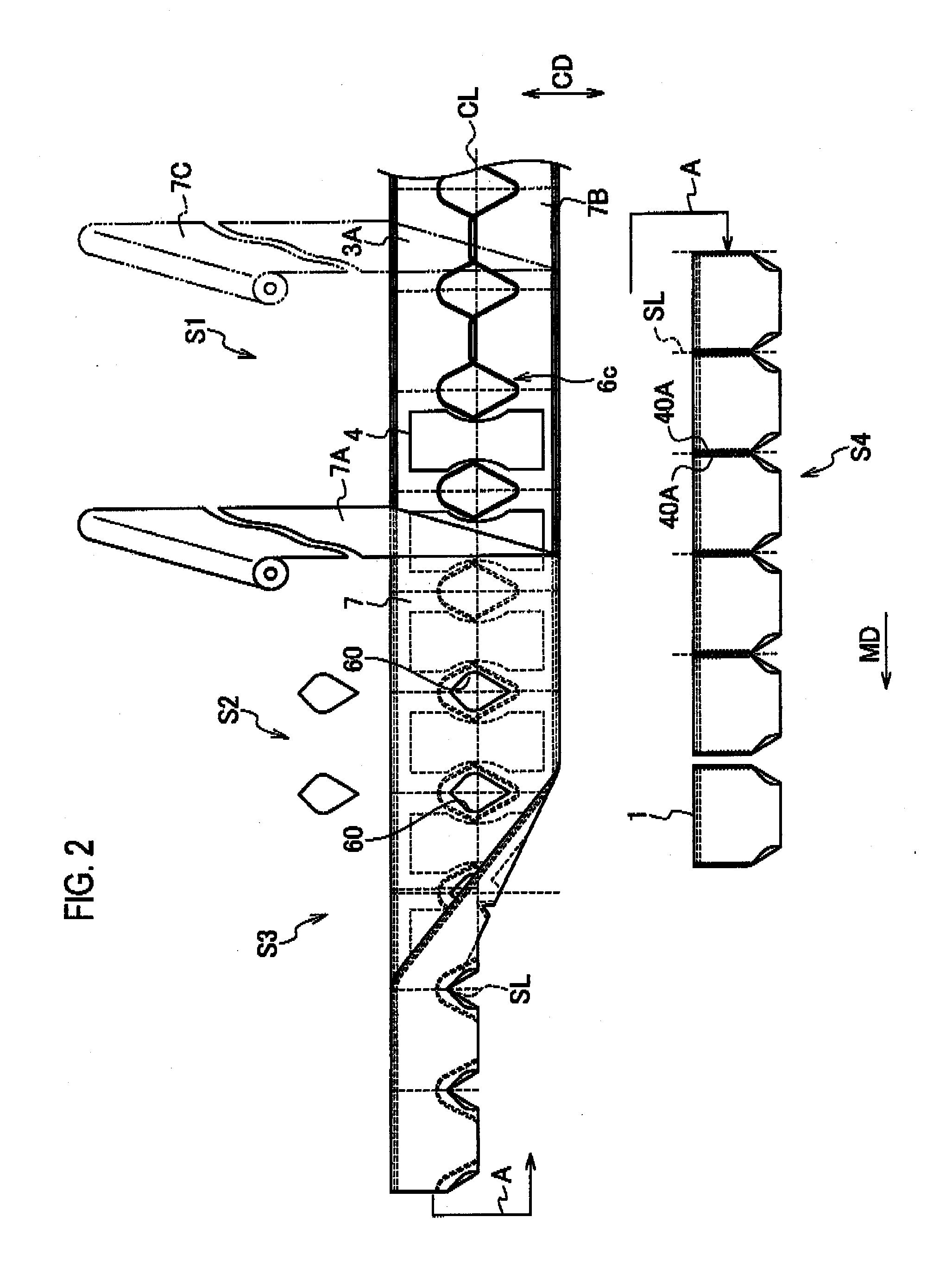
[0038]In the present embodiment, description will be given of: (1) configuration of absorbent article, (2) Manufacturing Method of Absorbent Article, (3) Entire Configuration of Manufacturing Apparatus of Absorbent Article, (4) Detailed Configuration of Web Position Guiding Mechanism, (5) Operation of Manufacturing Apparatus of Absorbent Article, (6) Advantages and Effects, and (7) Modified Example.

(1) Configuration of Absorbent Article

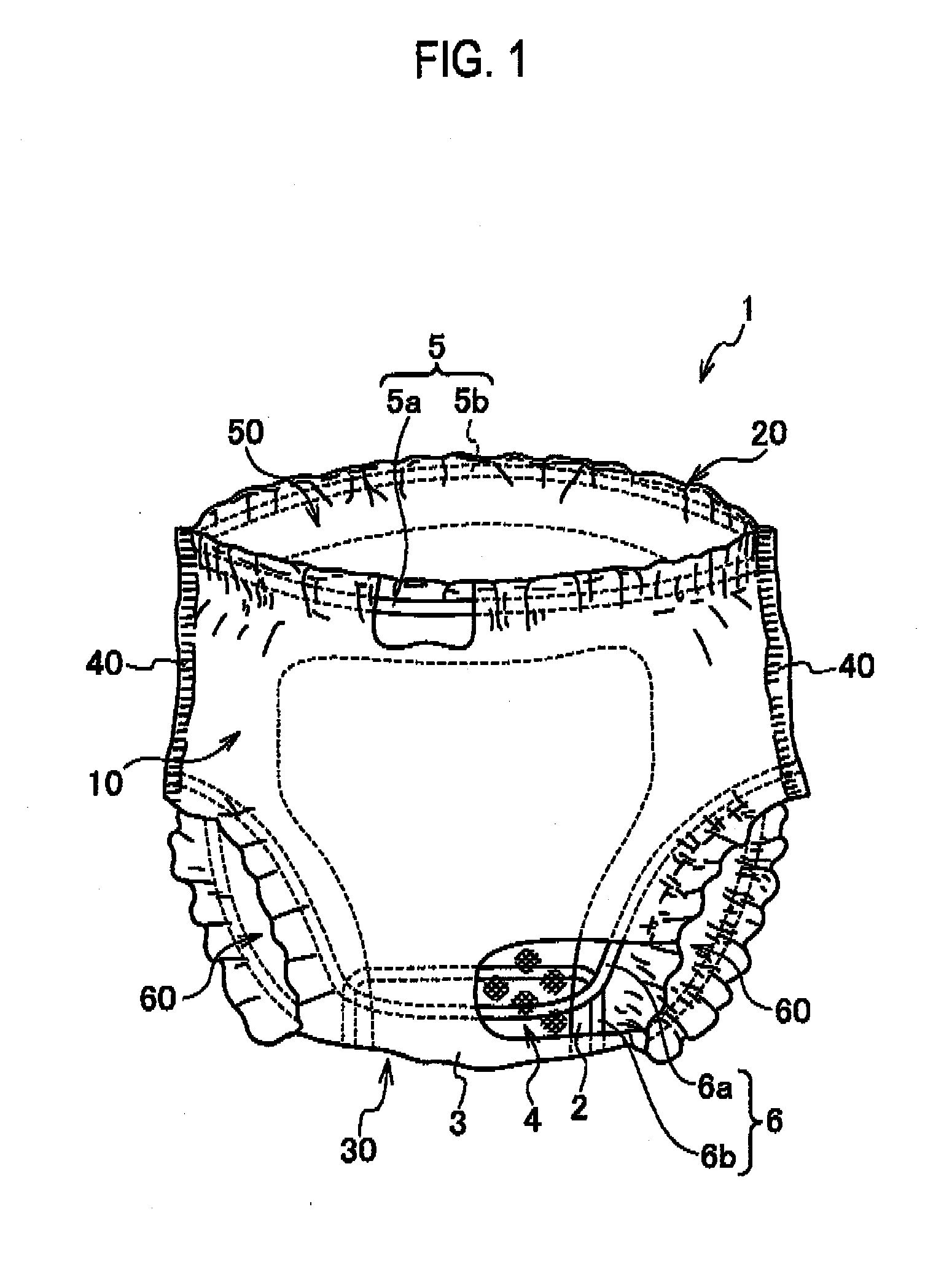
[0039]Firstly, a configuration of an absorbent article according to the present embodiment will be described by referring to the drawings. FIG. 1 is a perspective view showing an absorbent article according to the present embodiment. In the present embodiment, an absorbent article 1 is a disposable diaper for adults.

[0040]As shown in FIG. 1, the absorbent article 1 is mainly formed of a liquid permeable front sheet 2 which comes in contact with a skin of a target wearing the article (hereinafter, a wearer), a liquid impermeable back sheet 3 provided a...

second embodiment

[0110]According to the first embodiment mentioned above, the roller mechanism 120 in the work conveying mechanism 100 is formed to have the same shaft center.

[0111]According to a second embodiment, using FIG. 7, description will be given of a configuration including a roller different from that in the roller mechanism 120 of the first embodiment. FIG. 7 is a side view showing a web position guiding mechanism according to the present embodiment.

[0112]In the second embodiment below, points different from those in the first embodiment will be mainly described, and duplicated description will be omitted.

[0113]In the present embodiment, description will be given of (1) Detailed Configuration of Web Position Guiding Mechanism, (2) Advantages and Effects, and (3) Modified Example.

(1) Detailed Configuration of Web Position Guiding Mechanism

[0114]As shown in FIG. 7, a web position guiding mechanism (roller mechanism 120B) in the present embodiment is characterized by including an outer side ...

third embodiment

[0120]According to the first embodiment and the second embodiment mentioned above, the web position guiding mechanism in the work conveying mechanism 100 is the roller mechanism including the roller.

[0121]According to a third embodiment, the web position guiding mechanism in the work conveying mechanism 100 is provided upstream of the passing point P2 in the conveyance direction of the third web 7C.

[0122]FIG. 9 is a perspective view showing an entire configuration of a manufacturing apparatus of an absorbent article according to the third embodiment of the present invention. FIG. 10 is a side view (a view seen in the direction of an arrow C of FIG. 9) showing the entire configuration of the manufacturing apparatus of the absorbent article according to the third embodiment of the present invention. In the third embodiment below, points different from those in the first embodiment will be mainly described, and duplicated description will be omitted.

[0123]In the present embodiment, des...


PUM

PropertyMeasurementUnit
Diameteraaaaaaaaaa
Widthaaaaaaaaaa

Abstract

A work conveying mechanism according to the present invention includes a rotation drum in which an adsorbing pad for adsorbing an absorber is provided. The work conveying mechanism rotates the rotation drum and arranges the absorber on a third web being conveyed. In an outer shape of the work adsorbed by the adsorbing pad, an outer edge portion thereof is closer to a shaft center side of the rotation drum than a central portion thereof is. A work conveying mechanism includes a roller mechanism provided on a side of the third web opposite to the rotation drum side and configured to locate the third web on the adsorbing pad side. At a passing point, the roller mechanism arranges an outer edge portion of the third web in a width direction on a shaft center side of the rotation drum closer than a central portion thereof is.

Description

BACKGROUND OF THE INVENTION[0001]1. Field of the Invention[0002]The present invention relates to a manufacturing apparatus of an absorbent article and a manufacturing method of an absorbent article, the apparatus provided with a rotation drum including an adsorbing part that adsorbs a work, which is a component forming a part of the absorbent article.[0003]2. Description of the Related Art[0004]Conventionally, in a manufacturing process of absorbent articles such as disposable diapers, widely used is a manufacturing apparatus of an absorbent article including a work conveying mechanism In the work conveying mechanism, a band-like body formed of successive works, each of which is a component of an absorbent article, is cut into absorbent sheets. The work is specifically an absorbent sheet that absorbs liquid excreted from a target wearing the article (for example, a human body). In addition, the work conveying mechanism rotates an arrangement direction of the absorbent sheet by 90 de...

Claims


Application Information

Patent Timeline
IPC IPC(8): B32B37/12
CPCA61F13/15723A61F13/15764A61F13/15804Y10T156/1773Y10T156/1008Y10T156/1007Y10T156/101Y10T156/1734Y10T156/1771Y10T156/1768Y10T156/1761Y10T156/1075Y10T156/1077B32B37/02B65G31/04A61F13/49
Inventor YAMAMOTO, HIROKI
Owner UNI CHARM CORP
Learn More