
Video display device, imaging apparatus, and method for video display

Inactive Publication Date: 2010-05-20
SONY CORP
View PDF7 Cites 4 Cited by
  • Summary
  • Abstract
  • Description
  • Claims
  • Application Information

AI Technical Summary

Benefits of technology

[0017]It is desirable that an area having a specific brightness level can be indicated favorably in video which is being captured so that the indication does not obstruct the video.
[0022]According to the embodiment of the present invention, only the area in the specified range of brightness values is displayed in color based on the original input video signals. Thus, which portion is relevant to the specified range of brightness values can be easily determined in displayed video. Furthermore, the area in the specified range of brightness values is distinguished from the other area by the presence or absence of color. To distinguish the two areas, an extra is not superimposed on displayed video. Thus, any portion of the video can be easily viewed.
[0023]Accordingly, for example, the brightness value of the area in the specified range of brightness values can be easily set to a specified level and the area having the specified level can be easily focused on in the displayed video.

Problems solved by technology

Disadvantageously, it is difficult to check a video segment corresponding to the area in the video displayed on an electronic viewfinder.
Accordingly, even when a user intends to perform focusing adjustment so that the target brightness area is in focus, it is difficult to perform accurate focusing adjustment.
For example, when imaging conditions are adjusted so that the above-described skin color area has a brightness level of 50% and it is further necessary to accurately focus on the skin color portion, it is difficult to perform focusing adjustment because the stripe pattern obstructs focusing.
Accordingly, it is difficult to easily perform an operation of changing the brightness level for zebra pattern addition.
In the case where brightness level adjustment is performed while the zebra pattern is added to a portion, therefore, it is difficult to change the brightness level for zebra pattern addition.
Disadvantageously, the ease of operation is not good.

Method used


Image

  • Video display device, imaging apparatus, and method for video display
  • Video display device, imaging apparatus, and method for video display
  • Video display device, imaging apparatus, and method for video display

Examples


Embodiment Construction

[0030]Embodiments of the present invention will be described in the following order:

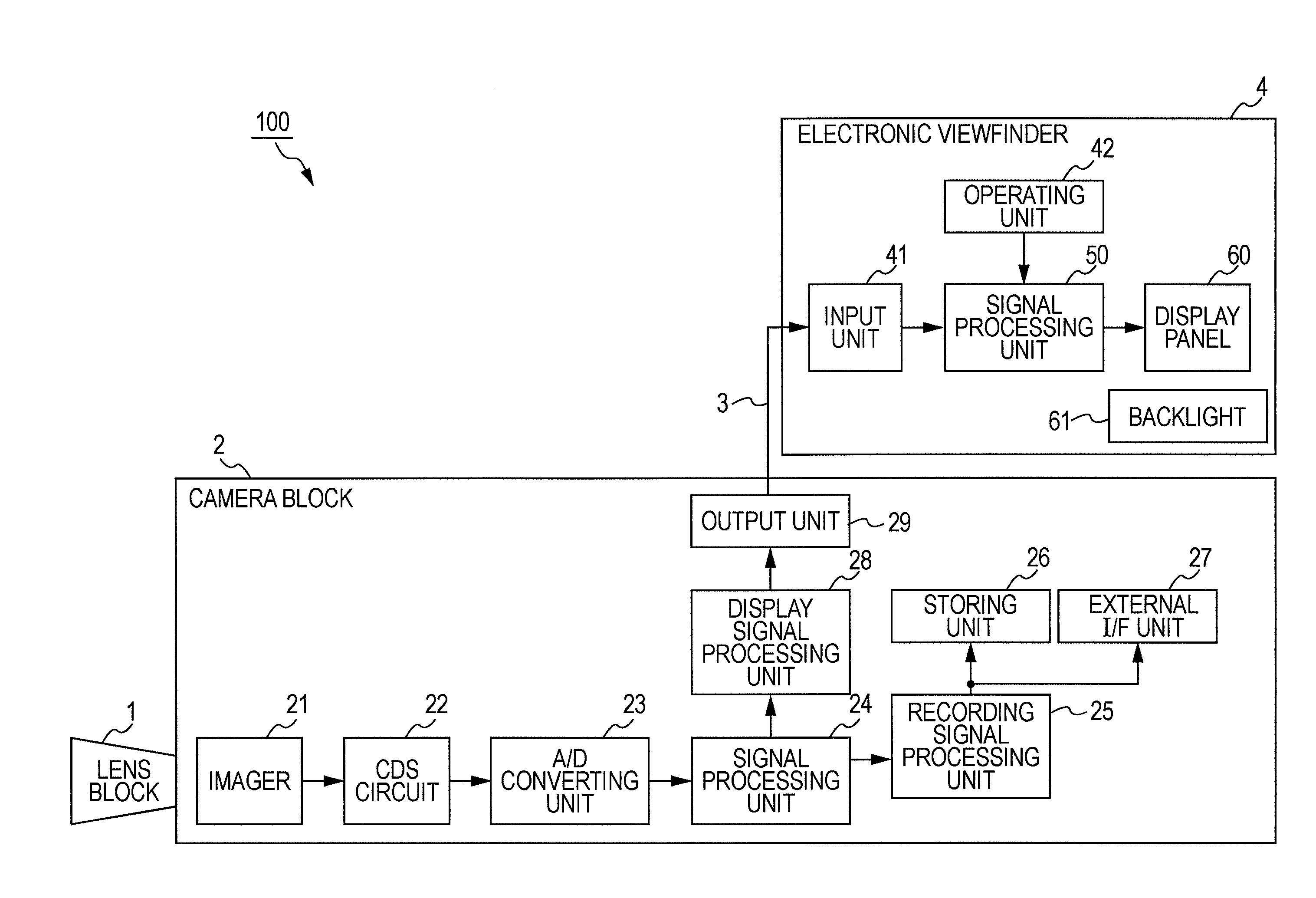
[0031]1. Exemplary Configuration of Imaging Apparatus (FIG. 1);

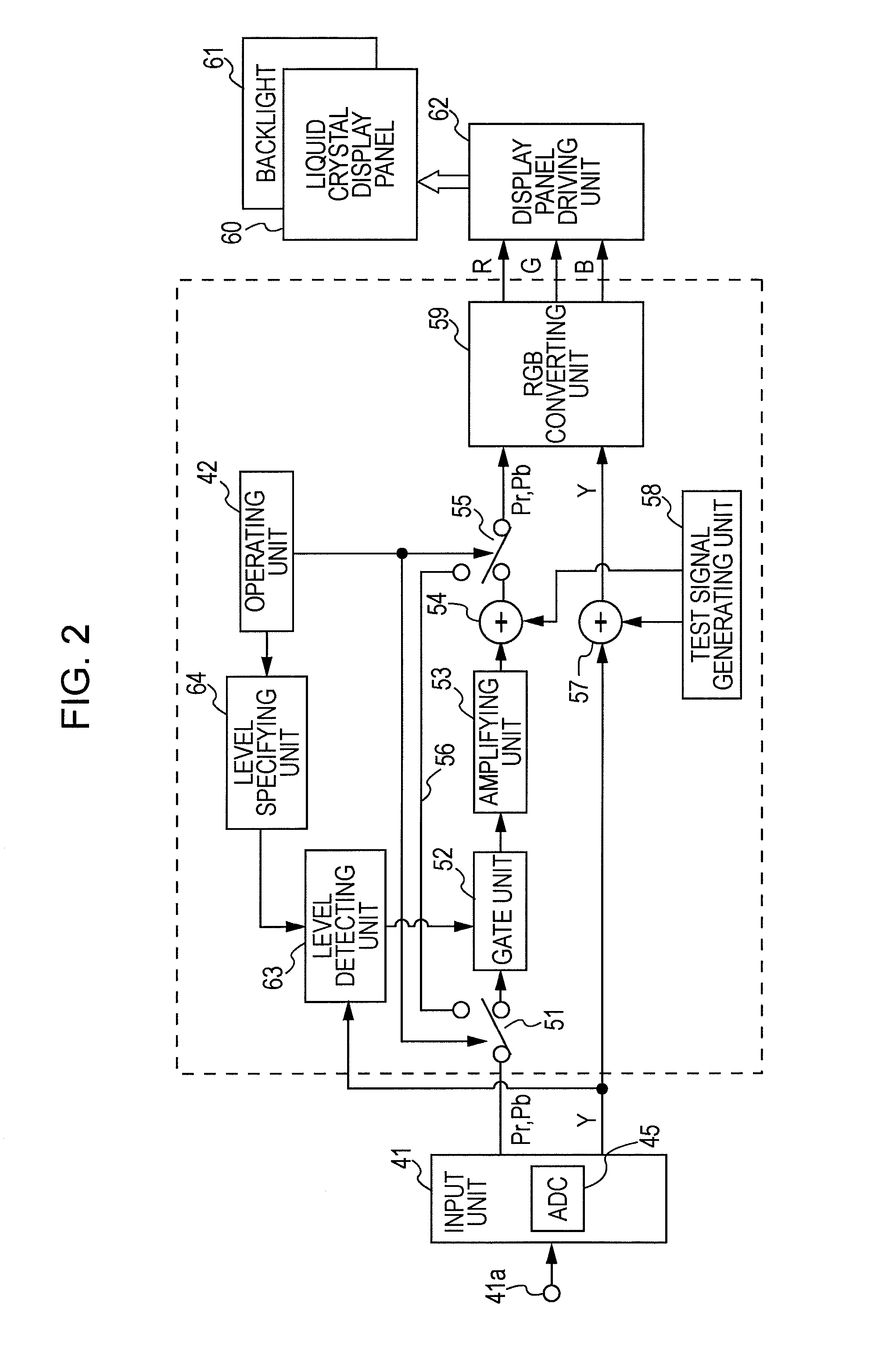
[0032]2. Exemplary Configuration and Operation of Electronic Viewfinder (FIGS. 2 and 3);

[0033]3. Display Examples (FIGS. 4 and 5); and

[0034]4. Modifications.

[0035]1. Exemplary Configuration of Imaging Apparatus

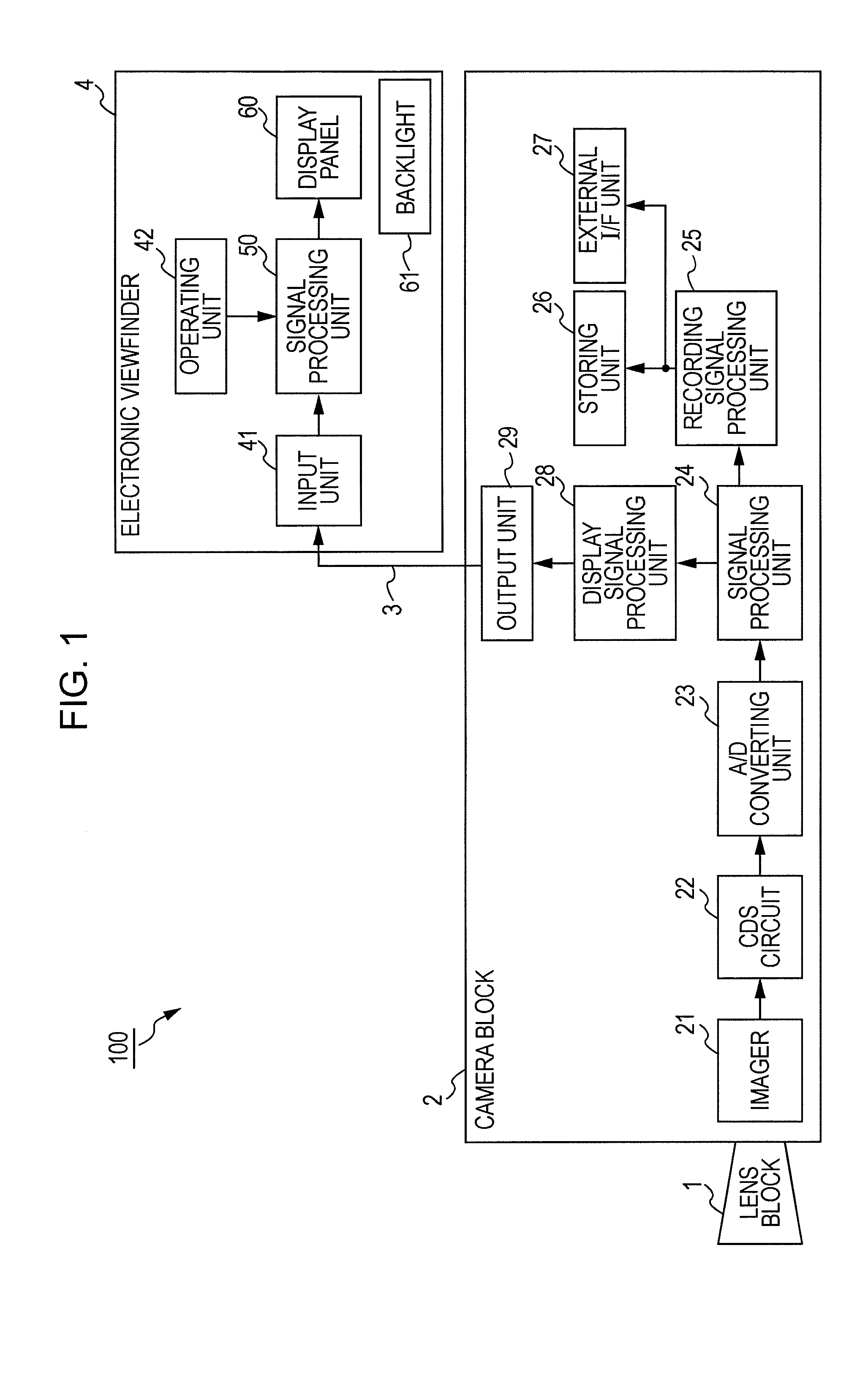
[0036]FIG. 1 illustrates an internal exemplary configuration of an imaging apparatus according to an embodiment of the present invention. Referring to FIG. 1, the imaging apparatus, indicated at 100, includes a lens block 1 that takes subject light into the imaging apparatus 100, a camera block 2, and an electronic viewfinder 4. In this embodiment, the electronic viewfinder 4 is configured to be detachable from the camera block 2.

[0037]The lens block 1 includes lenses for image capture and further includes a focusing ring (not shown) for adjusting the position of a lens for focusing adjustment and an iris mechanism (not illustrated)...


PUM


Abstract

A video display device includes a brightness range specifying unit configured to specify a range of brightness values for highlight, a signal processing unit configured to detect signals relevant to an area other than an area in the brightness range specified by the brightness range specifying unit from input video signals, suppress color components of the detected signals, and not suppress color components of signals relevant to the area in the specified brightness range, and a display unit configured to display video based on the video signals processed by the signal processing unit, the unit being capable of performing color display.

Description

BACKGROUND OF THE INVENTION[0001]1. Field of the Invention[0002]The present invention relates to a video display device suitably applied to an electronic viewfinder that displays video obtained by image capture through, for example, an imaging apparatus, an imaging apparatus including the video display device, and a method for allowing the video display device to display video.[0003]2. Description of the Related Art[0004]Imaging apparatuses (video cameras) for broadcast stations or business purposes are designed so that various imaging condition adjustments, such as focusing adjustment and brightness level adjustment, can be performed manually in order to increase the flexibility of video expression. Enabling the manual adjustments allows for image capture reflecting the purpose of a producer or an operator who performs shooting works.[0005]The operator, who performs shooting works, views video displayed on an electronic viewfinder of such a video camera to check whether intended vi...

Claims


Application Information

Patent Timeline
IPC IPC(8): H04N9/68H04N5/66
CPCH04N9/77H04N5/23293H04N23/633
Inventor OOBA, YUUJI
Owner SONY CORP
Learn More